News
Rich project cases across industries, showing real implementation and proven technical strength.Caustic soda flakes, also known as sodium hydroxide flakes, are widely used in industries such as chemical processing, water treatment, pulp and paper, textiles, and alumina refining. Their highly hygroscopic nature, corrosive properties, and tendency to cake or degrade when exposed to moisture pose significant challenges during material handling. Traditional mechanical conveying methods often lead to equipment fouling, safety hazards, and material loss. A dedicated pneumatic conveying equipment system solution designed specifically for caustic soda flakes addresses these challenges by ensuring sealed, automated, and gentle transport. In the modern industrial landscape of 2026, where production efficiency, workplace safety, and environmental compliance are non‑negotiable, selecting the right pneumatic system is not just a technical decision but a strategic one.
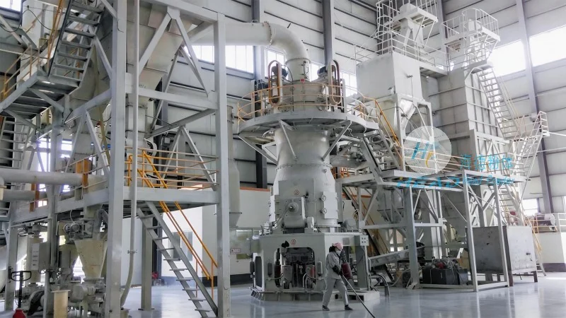
The core objective of a caustic soda flakes pneumatic conveying system is to move the material from storage points—such as big bags, silos, or tipping stations—to process equipment like mixers, dissolvers, or packaging lines without exposing the product to moisture, dust, or mechanical damage. Unlike free‑flowing powders, caustic soda flakes have irregular particle shapes and a tendency to absorb atmospheric humidity, which can cause bridging, sticking, and even chemical reactions inside conveying pipelines. Therefore, the system must incorporate precise airflow control, material conditioning, and robust component materials that resist corrosion. A well‑engineered pneumatic solution not only extends equipment life but also reduces downtime, lowers energy consumption, and improves product quality consistency. This article provides an in‑depth look at the design principles, key components, operational parameters, and real‑world considerations for caustic soda flakes pneumatic conveying equipment, with practical insights drawn from industry best practices.
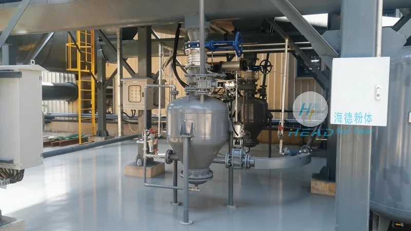
A complete pneumatic conveying system for caustic soda flakes typically consists of a material feeding device, a conveying pipeline, a separation unit, a dust collection system, and a control panel. Each component must be selected and configured to match the specific physical and chemical properties of the flakes.
Two primary pneumatic conveying modes are applicable to caustic soda flakes: dilute phase (low pressure) and dense phase (high pressure). The choice depends on factors such as conveying distance, material friability, and budget.
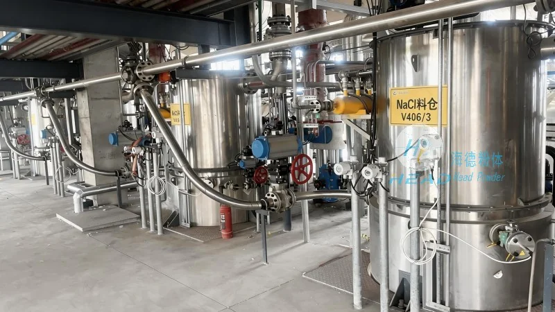
In many 2026 applications, manufacturers are adopting hybrid systems that combine dilute phase for short transfers and dense phase for longer legs, optimizing both capital investment and operational performance. headpowder’s engineering team analyzes the specific particle size distribution, moisture content, and flowability of each client’s caustic soda flakes to recommend the most appropriate conveying mode, supported by computational fluid dynamics (CFD) simulations.
Caustic soda flakes present two major engineering challenges: hygroscopicity and corrosivity. Addressing these effectively separates a reliable system from one that requires frequent maintenance.
headpowder has implemented systems in multiple caustic soda processing plants where moisture‑related downtime was reduced by over 40% through the integration of heated pipeline jackets and low‑dew‑point air supply. These engineering details, while adding some upfront cost, provide long‑term reliability that translates into measurable ROI.
Proper sizing of the pneumatic conveying system is crucial for achieving the desired throughput without excessive energy consumption or pipe wear. Key parameters include pipe diameter, air velocity, pressure drop, and material‑to‑air ratio.
headpowder provides a detailed sizing questionnaire to clients, covering material density, particle size distribution, target capacity, and site layout. Using proprietary software, the engineering team generates optimized pipeline routing and component specifications, ensuring that the system operates at peak efficiency while accommodating future process changes.
Handling caustic soda flakes involves significant safety risks, including chemical burns, respiratory irritation, and fire hazards if the fine dust becomes airborne. A well‑designed pneumatic conveying system mitigates these risks through containment, monitoring, and fail‑safe controls.
headpowder offers a comprehensive after‑sales support package that includes remote diagnostics, spare parts inventory management, and annual system audits. One chemical plant client reported a 25% reduction in unplanned maintenance costs after implementing headpowder’s predictive maintenance program, which uses vibration analysis and pressure trend monitoring to forecast component wear.
To illustrate the practical benefits, consider a mid‑scale caustic soda flakes processing facility in Southeast Asia that upgraded from a manual bag‑dumping to a fully automated pneumatic conveying system. Prior to the upgrade, the plant faced chronic issues: workers exposed to caustic dust, high labor costs for manual handling, and frequent production stoppages due to blockages in the bucket elevator. The facility required a system capable of conveying 3 t/h of flakes from a storage silo to two dissolving tanks located 60 meters away, with two 90‑degree bends.
headpowder designed a dense‑phase system using a pressure vessel feeder (blow tank) with a capacity of 1.5 m³. The pipeline was 100 mm diameter 316L stainless steel, with a 5D bend radius. A desiccant dryer provided air at –30°C dew point. The system included automatic blow‑down cycles to clear the line of any residual material after each batch. Installation was completed within 4 weeks, and the system achieved a consistent conveying rate of 3.2 t/h with less than 1% particle breakage. The plant’s operator reported a 70% reduction in manual labor, elimination of dust in the working environment, and a payback period of 14 months. This case demonstrates that a properly designed caustic soda flakes pneumatic conveying equipment system solution not only improves operational efficiency but also enhances workplace safety and regulatory compliance.
Implementing a pneumatic conveying system for caustic soda flakes is a complex undertaking that requires deep knowledge of material behavior, airflow dynamics, and corrosion engineering. A generic system design will lead to frequent blockages, high maintenance costs, and potential safety incidents. Instead, a customized solution that accounts for the specific particle properties, environmental conditions, and production goals is essential. As the industry moves toward higher automation and stricter environmental standards in 2026, investing in a robust pneumatic conveying system is a forward‑looking decision that directly impacts profitability and sustainability.
headpowder has accumulated extensive field experience in designing and installing caustic soda flakes pneumatic conveying equipment systems across multiple industries. From initial feasibility studies to commissioning and after‑sales support, the company’s engineers apply proven methodologies and advanced simulation tools to deliver systems that perform reliably year after year. Whether you are looking to replace an outdated mechanical conveyor or building a new greenfield plant, a well‑engineered pneumatic solution can transform your material handling operations. For a detailed discussion on how headpowder can assist with your specific application, please contact our technical team. (咨询热线:156-6277-7102)
By focusing on the unique challenges of caustic soda flakes—moisture control, corrosion resistance, particle integrity, and safety—this article has outlined the critical elements of a successful pneumatic conveying system. The key takeaway is that a tailored approach, supported by rigorous engineering and realistic operational data, yields the best long‑term results. As you evaluate your next material handling investment, remember that the right system not only moves product but also protects your people, your equipment, and your bottom line.

 Shandong headpowder Engineering Co., Ltd.
 156-6277-7102(Manager Zhang)
  0531-83386006
  Jinan City, Shandong Province, China
服务热线
微信咨询
回到顶部