News
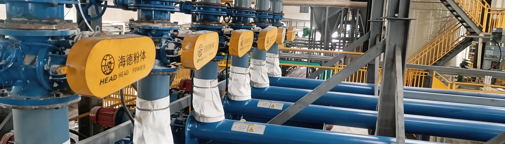
Rich project cases across industries, showing real implementation and proven technical strength.Dry cement ash pneumatic conveying systems are fundamental to the efficient and environmentally responsible management of bulk materials in modern cement production, power generation, and construction material processing industries. As the global push for carbon neutrality intensifies and raw material costs continue to fluctuate, the need for a reliable, low-maintenance, and energy-efficient conveying solution has never been more critical. Pneumatic conveying technology, specifically tailored for dry cement ash, offers a closed-loop, dust-free method that not only preserves material quality but also aligns with increasingly stringent emission standards. In 2026, the market for pneumatic conveying systems is projected to grow by approximately 7.2% year-over-year, driven by the expansion of infrastructure projects in emerging economies and the retrofitting of aging industrial plants in developed regions. This growth trajectory underscores the urgency for plant managers and procurement specialists to understand the intricacies of system design, component selection, and operational optimization.
At its core, a dry cement ash pneumatic conveying system utilizes pressurized air to transport fine, abrasive, and hygroscopic powders through pipelines from one point to another—typically from silos or hoppers to blending tanks, packing machines, or loading stations. The system’s architecture must address the unique physical and chemical properties of cement ash, including its particle size distribution (typically 1–100 microns), bulk density (ranging from 0.9 to 1.6 t/m³), and high abrasiveness. Moreover, cement ash’s tendency to absorb moisture and form agglomerates demands meticulous control of air quality and pipeline material selection. Over the past decade, advances in automation and remote monitoring have transformed these systems from simple mechanical conveyors into intelligent, self-regulating networks that minimize human intervention while maximizing throughput.
Pneumatic conveying systems for dry cement ash generally operate under two primary modes: dilute phase and dense phase. Dilute phase conveying suspends the material in a high-velocity air stream, typically between 15 and 30 meters per second, which is suitable for shorter distances and lower capacities but generates more wear on pipelines due to particle impact. Dense phase conveying, on the other hand, moves the material as a plug or slug at lower velocities (typically 3–10 m/s), using pressure vessels or blow tanks to push the material through the line. This method reduces pipeline abrasion and energy consumption by up to 40%, making it a preferred choice for longer distances or when handling fragile or abrasive materials like cement ash.
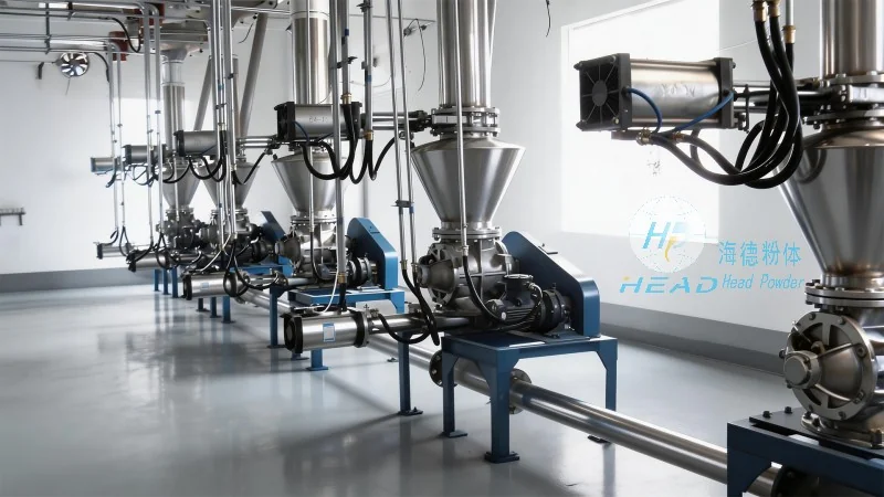
The selection between dilute and dense phase depends on factors such as conveying distance (commonly 50–500 meters in typical plant layouts), required tonnage per hour (ranging from 10 to 200 t/h), and pipeline diameter (usually 100–300 mm). For example, a typical 500-meter dense phase system handling 50 t/h of fly ash at a pressure of 2–4 bar can achieve a power consumption of 15–25 kWh per ton, significantly lower than an equivalent dilute phase system. Proper air-to-material ratio calculation, usually maintained between 1.5:1 and 3:1 by weight, is critical to prevent pipeline blockages and ensure consistent flow. Advanced systems now incorporate real-time pressure sensors and flow meters to dynamically adjust air supply, maintaining optimal conditions even when material properties vary due to changes in moisture content or particle fineness.
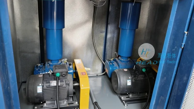
A robust dry cement ash pneumatic conveying system integrates several specialized components, each playing a distinct role in ensuring reliable operation and longevity. The selection of these components must be based on the specific characteristics of cement ash and operational requirements. Below is a detailed breakdown of the essential subsystems:
Energy costs represent a significant portion of the total ownership cost for a dry cement ash pneumatic conveying system—often 30–50% of annual operating expenses. Therefore, optimization strategies must be embedded from the design stage through daily operation. One proven approach is the implementation of variable-speed conveyors and dual-pressure air supply lines. By using a lower pressure (e.g., 2 bar) for long, straight sections and a higher pressure (e.g., 5 bar) only for high-resistance bends or vertical lifts, overall energy consumption can be reduced by up to 30% compared to a single-pressure design. Furthermore, integrating a waste heat recovery unit to preheat the conveying air using exhaust from the kiln or clinker cooler can lower the compressor load and reduce carbon footprint.
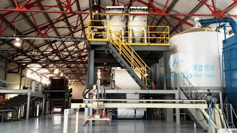
Another critical factor is the optimization of conveying velocity. As noted earlier, operating at the lowest possible velocity that maintains suspension prevents particle attrition and pipe wear. Advanced control algorithms now use real-time velocity measurement via Doppler sensors to maintain the velocity within a ±10% band of the setpoint, compensating for changes in material density or air temperature. For example, a cement plant in Shandong province reported a 22% reduction in pipeline replacement costs after retrofitting its dilute phase line with a dense phase booster station and velocity optimization logic, achieving a payback period of less than 18 months.
Material conditioning also plays a role: adding a small amount of dry air to the ash silo (maintaining a positive pressure of 50–100 Pa) prevents ambient moisture ingress and ensures free-flowing material at the feeder inlet. Similarly, using a vibrating bin activator with a flow-promoting insert can eliminate bridging and rat-holing, which commonly cause feed interruptions. Headpowder’s engineering team frequently recommends these auxiliary measures as part of a holistic system design, ensuring that the conveying system does not become the bottleneck in the production line.
Looking ahead to 2026 and beyond, several trends are reshaping the design and deployment of dry cement ash pneumatic conveying systems. First, the adoption of hybrid systems that combine both pneumatic and mechanical conveying (such as a pneumatic lift followed by a belt conveyor) is gaining traction for plants with complex layouts. This approach leverages the dust-free advantage of pneumatic transport for vertical or inclined sections while using lower-energy mechanical conveyors for horizontal runs. Second, the use of additive manufacturing for custom pipeline elbows and valve components allows for complex internal geometries that reduce turbulence and wear—some experimental designs have shown a 70% reduction in erosion rate compared to standard radius bends.
Third, the integration of Internet of Things (IoT) sensors and digital twin technology is enabling remote diagnostics and predictive maintenance. A digital twin of the conveying system, fed by real-time sensor data, can simulate the impact of changing material properties or operating parameters, allowing operators to test adjustments before implementing them physically. Several major cement producers have already deployed such systems, reporting a 15–20% reduction in unplanned downtime and a 10–12% increase in overall equipment effectiveness (OEE). Moreover, cloud-based analytics platforms now allow centralized monitoring of multiple plants, enabling corporate engineering teams to benchmark performance across sites and share best practices.
Regulatory pressures are also driving innovation. The European Union’s revised Industrial Emissions Directive (IED) and similar regulations in other regions are pushing particulate emission limits downward toward 5 mg/Nm³ for new installations. This has accelerated the development of multi-stage filtration systems and leak-proof rotary valve designs. In China, the implementation of the “Ultra-Low Emission” standard for the cement industry has led to a surge in demand for high-performance pneumatic systems that can maintain seal integrity under varying pressure conditions. Headpowder has responded to these requirements by developing a specialized rotary valve with a double-lip seal and a pressure compensation cavity, which has achieved a leakage rate of less than 0.1% of the conveying air volume in third-party tests.
To illustrate the practical benefits of well-designed pneumatic conveying systems, consider two representative installations. The first involves a large cement grinding station in Southeast Asia that required upgrading its ageing dilute phase system handling 80 t/h of pulverized fly ash from a silo 120 meters away. The original system suffered from frequent blockages and high energy consumption—28 kWh/t. After replacing the rotary valves and installing a dense phase blow tank system with a ceramic-lined pipeline and adaptive control, the specific energy consumption dropped to 16 kWh/t, and the average annual downtime due to blockages decreased from 320 hours to under 40 hours. The client reported a total cost reduction of 35% in the first year of operation.
Another case involves a cement terminal in Northern Europe that needed to load trucks and ships with dry cement ash from multiple silos. Headpowder designed a modular pneumatic conveying network with multiple pick-up points and a single discharge route, using a centralized control system to prioritize loading based on real-time inventory and shipping schedules. The system achieved a peak transfer rate of 120 t/h while maintaining a noise level below 75 dB(A) and dust emissions below 5 mg/Nm³. The client’s operational data showed a 98.7% uptime over a 12-month period, largely due to the redundant air supply lines and self-cleaning filter cartridges that minimized manual maintenance. These results demonstrate how proper system engineering—not just component selection—delivers measurable, long-term value.
Even the most sophisticated pneumatic conveying systems require a disciplined maintenance program to sustain performance over a 15–20 year lifecycle. The first priority is pipeline integrity inspection. Using ultrasonic thickness gauging at predetermined intervals (e.g., every six months at bends and every 12 months at straight sections) allows early detection of wear hotspots. A typical replacement threshold is 60% of original wall thickness for carbon steel pipes. Second, rotary valve seals and blow tank gaskets should be inspected quarterly, with replacement intervals of 2–3 years depending on operating pressure and material abrasiveness. Seals that are allowed to degrade can cause air leakage, which increases energy consumption and reduces conveying capacity.
Third, filter bag condition should be monitored via differential pressure trends. A sudden increase of 50 Pa over the baseline typically indicates bag blinding or rupture, requiring immediate replacement. Regular compressed air quality testing—dew point and oil content checks—is equally vital, as moisture contamination can lead to ash hardening inside pipelines and filters. Additionally, the control system logs should be reviewed monthly to identify subtle trends, such as a gradual increase in conveying pressure that might indicate incipient pipeline fouling. Many operators now employ thermal imaging cameras to detect hot spots on pipeline bends, which can signal local material buildup or internal wear. By combining these proactive measures with a spare parts inventory strategy (stocking critical items like rotary valve rotors, ceramic sleeves, and control board modules), plant downtime can be minimized to fewer than 50 hours per year even in high-utilization environments.
With decades of focused engineering experience in dry bulk material handling, headpowder has developed a comprehensive understanding of the challenges unique to cement ash and other fine powders. Our design philosophy centers on creating systems that are not only technically robust but also cost-effective over the long term. We employ advanced CFD modeling during the proposal phase to predict flow behavior, optimize pipeline routing, and size components with precision—reducing the risk of underperformance or over-engineering. Every system we deliver undergoes factory acceptance testing using a standardized cement ash simulant, validating throughput, pressure drop, and dust emission levels before shipment.
Beyond hardware, headpowder provides a full suite of aftermarket services, including remote monitoring, predictive maintenance analytics, and on-site training for plant operators. Our engineering team stays abreast of evolving regulations and material science advances, allowing us to recommend upgrades such as ceramic-lined tees or low-energy booster stations that can be retrofitted to existing systems without major infrastructure changes. This commitment to continuous improvement has earned us long-term partnerships with cement producers in over 20 countries, many of whom rely on our systems for their most critical material transfer applications. As the industry moves toward tighter sustainability targets and higher automation, headpowder remains dedicated to delivering pneumatic conveying solutions that balance performance, reliability, and environmental responsibility. (咨询热线:156-6277-7102)

 Shandong headpowder Engineering Co., Ltd.
 156-6277-7102(Manager Zhang)
  0531-83386006
  Jinan City, Shandong Province, China
服务热线
微信咨询
回到顶部