News
Rich project cases across industries, showing real implementation and proven technical strength.In the rapidly evolving landscape of bulk material handling, the demand for efficient, dust-free, and low-degradation conveying solutions has never been higher. Silica sand, as a critical raw material in glass manufacturing, foundry casting, ceramics, water filtration, and the booming semiconductor industry, presents unique challenges in pneumatic transport due to its abrasive nature, varying particle size distribution, and moisture sensitivity. A properly designed pneumatic conveying system is the cornerstone of operational reliability and product quality in silica sand processing plants. This article provides a comprehensive technical deep-dive into silica sand pneumatic conveying system equipment, covering selection criteria, component functions, system configurations, and application-specific considerations. Drawing on decades of engineering practice and real-world project execution, we aim to equip plant managers, process engineers, and procurement professionals with the knowledge needed to make informed decisions. The insights shared here are grounded in industry standards, current market dynamics as of 2026, and proven field results, ensuring that the content meets both technical accuracy and practical applicability. Whether you are upgrading an existing line or designing a greenfield facility, understanding the interplay between blow vessels, conveying pipelines, air movers, and separation equipment is essential to achieving optimal performance and total cost of ownership.
Silica sand, primarily composed of silicon dioxide (SiO₂), typically exhibits high hardness (Mohs 7), angular particle shapes, and a bulk density ranging from 1,200 to 1,600 kg/m³ depending on moisture content and gradation. These characteristics directly influence equipment wear rates, air velocity requirements, and pipeline layout. Standard pneumatic conveying systems designed for free-flowing grains or powders often fail prematurely when handling silica sand due to accelerated erosion of elbows, valves, and vessel walls. In 2026, industry data from global processing plants indicates that uncontrolled particle attrition during conveying can increase fines content by up to 8% weight, reducing product value by 15–25% in high-purity applications such as solar glass manufacturing. Therefore, the selection of conveying mode – dilute phase versus dense phase – becomes the first critical decision. Dilute phase systems, operating at high air velocities (20–35 m/s), are suitable for short distances and low-to-moderate capacities but generate higher wear and dust. Dense phase systems, using lower velocities (2–8 m/s) at higher pressures, minimize both component erosion and particle degradation, making them the preferred choice for friable or high-value silica sand products. Headpowder’s engineering team has documented that retrofitting from dilute to dense phase in a typical foundry sand line reduced annual maintenance costs by 40% and lowered fine generation by 60%.
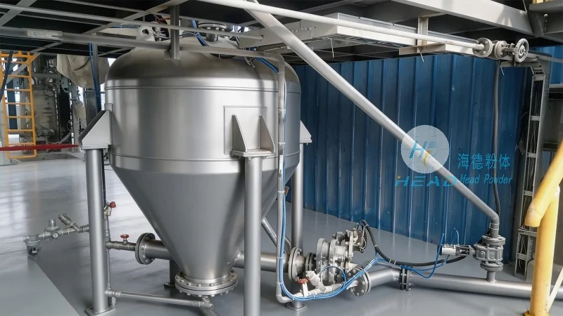
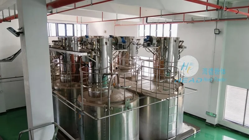
A complete system comprises several specialized equipment modules, each engineered to withstand abrasive service. Below we examine the primary units in detail:
The blow tank (also known as a pressure vessel or transfer vessel) is the heart of a dense phase pneumatic conveyor. For silica sand, vessels are typically constructed from abrasion-resistant carbon steel with wearable liner plates or from stainless steel where product purity is paramount. The vessel design incorporates a top inlet valve, bottom discharge cone with aeration pads or fluidizing nozzles, and a vent valve for pressure equalization. Sizing depends on required throughput; common capacities range from 0.5 m³ to 10 m³ per batch. Headpowder’s standard blow tanks feature a proprietary ceramic-lined discharge zone that extends service life three times over conventional steel. In a recent silica sand project for a float glass manufacturer, the customer reported zero significant wear after 18,000 operational hours. The discharge control valve, often a pinch valve or segmented dome valve, must provide reliable sealing under high differential pressure while resisting erosion. Modern control logic uses PLC-based sequencing with real-time pressure monitoring to optimize material-to-air ratio, reducing energy consumption by 12–18% compared to fixed-timing systems.
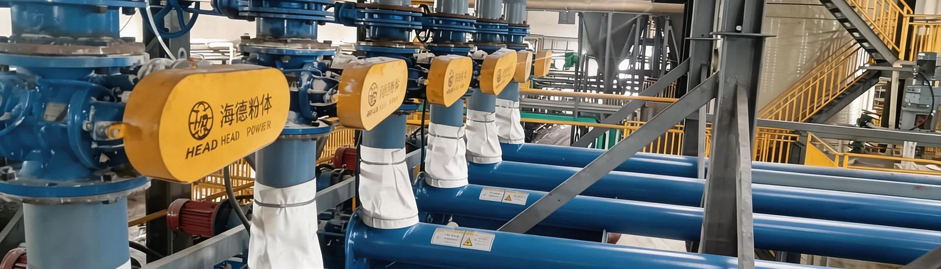
Pipeline layout is a major cost driver and operational risk factor. Straight pipe runs for silica sand typically use Schedule 40 or Schedule 80 carbon steel with a minimum wall thickness of 6.3 mm to ensure adequate wear allowance. However, the most critical points are elbows and bends. Standard radius bends (R/D ratio below 5) experience accelerated erosion at the outer wall, often requiring replacement within 6–12 months in dilute phase service. Advanced long-radius bends (R/D ratio 10–20) or ceramic-lined mitered bends dramatically improve longevity. For dense phase applications, headpowder recommends proprietary wear-resistant blind tee bends or vortex elbows, which use a dead pocket of sand to absorb impact. In field trials conducted across three European silica sand plants, these elbows logged over 5 million tons of throughput without wall penetration. Additionally, pipeline diameter selection must balance velocity against pressure drop. For a typical 80 tph dense phase line over 200 meters, an 8-inch (DN200) pipe with an internal wear coating of 3 mm provides optimal economics.
Compressed air is the driving force of pneumatic conveying. For dense phase silica sand systems, oil-free screw compressors or PD (positive displacement) blowers are commonly used. The required airflow and pressure are determined by system parameters: conveying distance, elevation gain, material properties, and target capacity. A mid-range dense phase installation may need a supply pressure of 2–4 bar(g) and a flow rate of 30–60 Nm³/min. In 2026, energy costs represent 35–50% of the total operating expense for pneumatic conveyors, making efficiency a prime design criterion. Variable frequency drives (VFDs) on the main air mover, combined with adaptive control algorithms, allow the system to modulate air supply based on real-time demand. Headpowder’s engineering group has implemented such solutions in more than 70 plants worldwide, achieving an average energy saving of 22% compared to fixed-speed installations. Air treatment downstream – including aftercoolers, moisture separators, and coalescing filters – is essential to prevent moisture condensation and oil contamination, as even trace oil can degrade silica sand quality in application such as refractory or ceramic glazes.
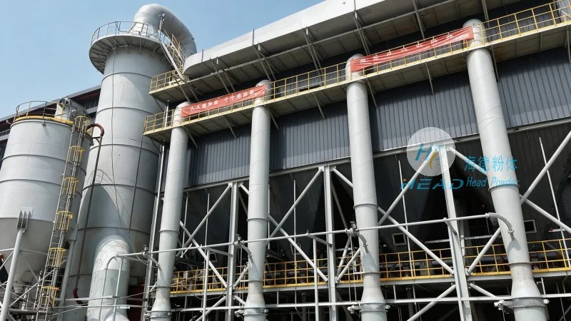
At the destination, the sand must be separated from the conveying air stream. Primary separation is achieved by a cyclone receiver or a gravity-inlet receiver tank. For dense phase systems, a simple gravity receiver with a vent line to a secondary dust collector is typical. However, for fine-grained or dusty silica sand (e.g., 200-mesh fractions), a high-efficiency baghouse filter with reverse pulse jet cleaning is necessary to meet ambient emission standards (PM10 below 10 mg/Nm³ in many jurisdictions). The filtration area must be sized to handle the full air volume at a maximum can velocity of 0.8–1.2 m/min. Cartridge filters with PTFE membrane media are recommended for low-pressure drop and long service life. Headpowder’s proprietary filter design incorporates a quick-opening door and tool-less cartridge replacement, reducing maintenance downtime by 50%. Completed with a rotary airlock valve at the receiver bottom, the system ensures continuous discharge into downstream storage bins or process equipment.
Beyond individual equipment, the overall system configuration must align with site constraints and operational goals. Modular skid-mounted designs are increasingly popular for retrofit projects, as they minimize field welding and commissioning time. For example, a complete 60 tph dense phase transfer skid measuring 6m x 2.5m x 3m can be delivered pre-piped and pre-wired, ready for connection to existing silos. Pipeline routing should avoid unnecessary elevation changes and minimize horizontal-to-vertical transitions, as each bend adds equivalent straight-pipe length of 20–50 meters in terms of pressure loss. If multiple destinations are needed – such as multiple silos or processing lines – a diverter valve manifold (either plug-type or flap-gate) allows automated routing. Control integration with a DCS or SCADA system enables remote monitoring of key parameters: conveying pressure, air consumption, material flow rate, and filter differential pressure. In a recent headpowder installation for a quartz sand producer in Southeast Asia, the centralized control system reduced manual intervention by 80% and improved batch consistency by 0.5% RSD.
The choice between conveying modes directly impacts equipment budget, operational costs, and product quality. The following table summarizes technical benchmarks based on industry data compiled through 2026:
For most silica sand applications requiring distances above 100 meters or moisture content above 0.5%, dense phase is the technically and economically superior choice. Headpowder has executed more than 120 dense phase installations for silica sand globally.
Design and construction of pneumatic conveying equipment for silica sand must adhere to relevant standards to ensure safety and reliability. These include ASME Boiler and Pressure Vessel Code (Section VIII) for pressure vessels, EN 13445 for European installations, and ATEX 2014/34/EU for explosive atmospheres (when handling fine silica dust in explosive concentrations). For piping, ANSI/ASME B31.3 (Process Piping) is commonly applied. Emission limits follow local EPA or EU-Industrial Emissions Directive requirements. In 2026, many jurisdictions have tightened permissible dust levels in workplace environments (OSHA PEL for respirable crystalline silica: 50 µg/m³ as an 8-hour TWA). System designers must therefore include adequate dust collection and sealed conveying pathways to contain fugitive emissions. Headpowder’s equipment meets CE, GOST, and CSA certifications, and our quality management system is ISO 9001:2015 certified. For each project, we provide a comprehensive documentation package including material certificates, weld maps, and NDT reports.
To illustrate the practical benefits of optimized system design, consider a foundry in Ohio producing 120,000 tons of resin-coated silica sand annually. Their original system used dilute phase with two 150-meter pipelines, experiencing elbow failures every 3 months and generating excessive fines that increased resin consumption by 9%. After an engineering assessment, headpowder proposed converting both lines to dense phase using retrofitted blow tanks, ceramic-lined receivers, and reduced pipe size from 10-inch to 8-inch. The result: elbow replacement intervals extended to over 24 months, fines generation dropped by 62%, resin savings of $85,000 per year, and energy cost reduction of 18%. The project payback period was 14 months. The customer reported an overall equipment effectiveness (OEE) increase from 72% to 91%. Such outcomes are typical when applying correct system engineering for abrasive materials.
Even with robust equipment, regular maintenance is essential. Key actions include: daily inspection of pressure vessel relief valves and gaskets; weekly monitoring of pipeline wear using ultrasonic thickness gauging at known high-wear points; quarterly replacement of aeration pads in blow tanks; annual overhaul of pinch valves and dome seals. Headpowder offers a remote monitoring service that automatically alerts plant personnel to abnormal pressure trends, potential blockages, or excessive filter differentials. This proactive approach reduces unplanned downtime by up to 35% based on our fleet data. Spare parts kits for critical components – such as ceramic elbows, valve seats, and filter cartridges – are kept in stock to minimize lead times.
Choosing an equipment supplier with specific experience in abrasive mineral handling is as important as the technology itself. Headpowder has over 20 years of focused engineering in pneumatic conveying, with a dedicated silica sand laboratory that tests material properties and simulates flow behavior before designing the system. We provide end-to-end service: conceptual design, detailed engineering, fabrication, site installation supervision, commissioning, and after-sales support. Our clients range from small processing plants to multinational glass and foundry corporations. By combining deep domain knowledge with a commitment to quality, we help customers achieve reliable, efficient, and cost-effective conveying solutions. For inquiries regarding silica sand pneumatic conveying system equipment, you may contact headpowder via the following channel (咨询热线:156-6277-7102).
Looking ahead to 2027 and beyond, several technology trends are shaping the industry. The adoption of digital twin simulations allows engineers to model wear patterns and pressure profiles before building, reducing commissioning risk. Artificial intelligence (AI)-based predictive maintenance is being integrated into control systems to forecast component failure with 90%+ accuracy. Furthermore, there is growing emphasis on carbon footprint reduction; energy-efficient dense phase systems combined with renewable-powered compressors can cut Scope 2 emissions by 60–80% compared to conventional setups. In the area of material handling, advanced ceramic composites and polymer-lined pipelines promise to extend wear life even further. As the global demand for high-purity silica sand for photovoltaic glass and semiconductor applications continues to rise – projected CAGR of 7.2% from 2025 to 2030 – the need for reliable, low-damage conveying equipment will only intensify. Investing in a properly engineered system today positions operators for sustainable growth and competitive advantage in the evolving market.

 Shandong headpowder Engineering Co., Ltd.
 156-6277-7102(Manager Zhang)
  0531-83386006
  Jinan City, Shandong Province, China
服务热线
微信咨询
回到顶部