News
Rich project cases across industries, showing real implementation and proven technical strength.Silica fume, also known as microsilica, is a byproduct of silicon and ferrosilicon alloy production. With an average particle size of 0.1 to 0.3 microns and a specific surface area exceeding 20,000 m²/kg, this ultra-fine powder presents unique handling challenges. Its low bulk density (typically 200–300 kg/m³ in its raw form), high angle of repose, and tendency to aerate and fluidize spontaneously make conventional mechanical conveying methods—such as screw conveyors or bucket elevators—inefficient, prone to clogging, and often unsafe due to dust explosion risks. Pneumatic conveying has emerged as the industry standard for transporting silica fume, offering enclosed, dust-free, and flexible solutions. This article provides a comprehensive, technically rigorous examination of pneumatic conveying methods for silica fume, covering system types, design parameters, material characteristics, operational considerations, and emerging trends through 2026. Whether you are a plant engineer, a procurement specialist, or a consultant evaluating bulk material handling systems, this guide aims to equip you with actionable knowledge to select, design, or optimize a silica fume conveying line.
Before delving into specific pneumatic methods, it is crucial to understand the physical and chemical properties of silica fume that directly influence system design. Silica fume is classified as a cohesive, aeratable powder. Its particle morphology is spherical, but the extreme fineness results in strong interparticle van der Waals forces, causing agglomeration. The material exhibits a very low tapped density—often between 400 and 600 kg/m³ after densification—and a high compressibility index (Carr index typically above 30%), indicating poor flowability. Additionally, silica fume is abrasive due to the presence of free silica (crystalline content up to 2–5% depending on the source), which accelerates wear on conveying pipes and components. The material's moisture content must be strictly controlled: even 0.5% moisture can lead to caking and bridging in silos and convey lines. Aeration properties are another critical factor: when aerated, silica fume behaves almost like a liquid, with a fluidized density dropping to 100–200 kg/m³. This characteristic is both a challenge and an opportunity in pneumatic conveying design. For pneumatic systems handling silica fume, the key design parameters include conveying velocity (typically 10–25 m/s for dilute phase, 3–8 m/s for dense phase), solid-to-air ratio (kg material per kg air), and pipe diameter (commonly 50–150 mm depending on throughput). Industry data from 2025 indicates that more than 75% of new silica fume handling installations worldwide now employ dense-phase pneumatic systems due to lower energy consumption and reduced pipe wear.
Dilute phase conveying, also known as suspension flow, is the most straightforward pneumatic method. In a dilute phase system, silica fume is entrained in a high-velocity airstream (typically 15–30 m/s) and transported through pipelines at relatively low solids concentrations (solid-to-air ratio of 5:1 to 15:1 by weight). The material is suspended throughout the pipe cross-section, moving at nearly the same velocity as the air. This method is widely implemented for short-distance transfers (up to 100–150 meters) and moderate throughputs (1–20 tons per hour). For silica fume, dilute phase systems commonly use positive pressure (blowers or compressors) upstream of the material feed point, with rotary airlocks or venturi feeders introducing the powder into the air stream. The advantage of dilute phase is its simplicity, lower initial capital cost, and ability to handle multiple pick-up points. However, the high velocity accelerates pipe wear—especially at bends—and can cause particle attrition, breaking down agglomerates and increasing dust generation. For silica fume, the abrasive nature of the material means that pipe bends should be lined with ceramic or basalt, and straight sections should use schedule 40 or 80 carbon steel with wall thickness no less than 6 mm. A real-world example: a cement additive plant in Jiangsu province successfully operates a dilute phase system conveying densified silica fume at 8 t/h over 80 meters using a 100 mm pipe and a 75 kW roots blower, achieving 99.8% material recovery with a baghouse filter. For applications where product integrity and minimal degradation are paramount—such as in high-performance concrete or refractory mixes—dilute phase may not be the optimal choice, as the high shear forces can alter particle size distribution.
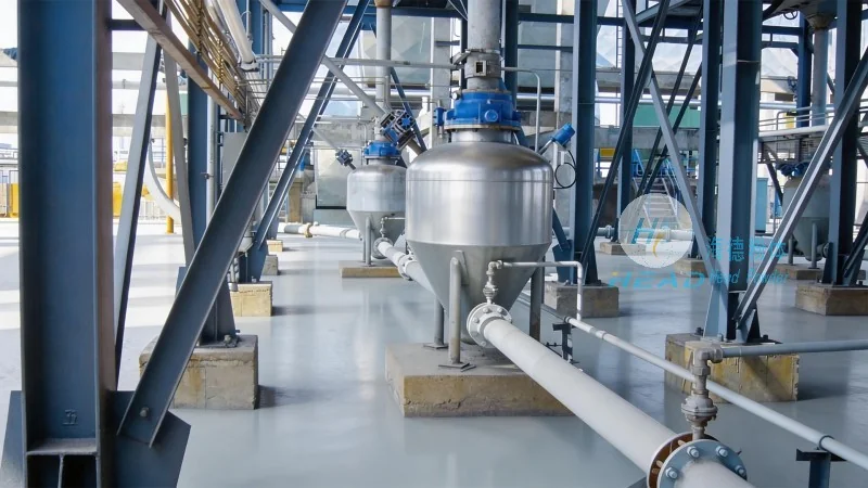
Dense phase pneumatic conveying operates at low velocities (2–8 m/s) and high solids concentrations (solid-to-air ratios of 20:1 to 80:1 or higher). The material moves in plugs or slugs through the pipeline rather than being fully suspended. This method is particularly well-suited for silica fume due to its excellent aeration and fluidization properties. Two main sub-categories exist: dense phase plug flow and dense phase fluidized flow. In plug flow, compressed air pushes discrete slugs of material separated by air gaps; in fluidized dense phase, the material is aerated to maintain a fluid-like state, enabling continuous flow at very low velocities. For silica fume, the fluidized dense phase approach is often preferred because the powder's natural tendency to aerate helps maintain stable flow without requiring sophisticated bypass or air injection systems. Dense phase systems offer multiple benefits: dramatically reduced pipe wear, lower energy consumption (up to 50% less compared to dilute phase for the same throughput), minimal particle degradation, and the ability to convey over longer distances (300 meters to 1 kilometer or more). Typical equipment includes pressure vessels (blow tanks or pressure pots) with a capacity of 0.5 to 10 m³, discharge valves, and a compressor supplying air at 5–8 bar. The design of the blow tank is critical: a conical bottom with a fluidizing membrane (porous ceramic or sintered metal) ensures uniform aeration and prevents bridging. A leading installer reported that a dense phase system for silica fume conveying at a microsilica processing plant in Shandong, with a pipeline length of 450 meters and a capacity of 12 t/h, consumes only 0.8 kWh per ton, compared to 1.6 kWh per ton for a comparable dilute phase system. Furthermore, pipe life extended from 18 months (dilute) to over 6 years (dense) due to reduced velocity. For companies prioritizing operational reliability and total cost of ownership, dense phase conveying is the dominant technology, with market share projected to exceed 80% among new silica fume handling installations by 2027.
Vacuum pneumatic conveying, also called suction conveying, operates under negative pressure (typically –0.3 to –0.6 bar). A vacuum pump or ejector creates suction at the receiving end, drawing both air and material through the pipeline from one or multiple feed points. For silica fume, vacuum systems are commonly used for unloading bulk tankers, feeding multiple silos from a single source, or handling material from open storage areas. The key advantage is a completely dust-free operation at the feed point, as the inward airflow prevents fugitive emissions. Vacuum systems are inherently safer when handling combustible dusts like silica fume (which is not explosive in the traditional sense but can produce hazardous dust clouds), as any leak would draw air inward rather than expelling material. However, vacuum systems are limited in conveying distance (typically under 100 meters due to pressure drop constraints) and are less efficient for high throughputs above 10 t/h. They also require careful design of the receiving hopper and filter separator to handle the sudden expansion of air. A typical vacuum system for silica fume would include a pickup nozzle or rotary airlock fed by a bag dump station, a 125 mm pipeline, a cyclone pre-separator, a cartridge filter with pulse-jet cleaning, and a liquid-ring vacuum pump. In 2024, headpowder designed a vacuum conveying system for a refractory manufacturer in Henan, enabling transfer of 6 t/h of silica fume from super sacks to two 50-ton silos over 60 meters. The system achieved a conveying velocity of 12 m/s with a solid-to-air ratio of 18:1 and maintained outlet dust concentration below 5 mg/Nm³, meeting local environmental standards. For plants with limited floor space or requiring multiple in-feed points, vacuum systems offer flexibility, but the higher specific energy consumption (1.2–1.8 kWh per ton) makes them less economical for continuous high-volume operations compared to dense phase pressure systems.
Regardless of the pneumatic method chosen, the performance and longevity of a silica fume conveying system depend critically on the quality and compatibility of individual components. Starting at the feed point, a reliable airlock or feeder is essential to prevent air loss while metering material. For dilute phase, rotary airlocks with hardened rotor tips and adjustable clearance (0.1–0.2 mm) are standard; for dense phase, dome valves or pinch valves provide superior sealing in high-pressure blow tank applications. Pipelines must be selected based on expected wear: seamless carbon steel with a hardness of at least 200 HB is common, but for highly abrasive silica fume, induction-hardened or ceramic-lined pipes can extend service life by 3–5 times. Bend geometry is critical: long-radius bends (R/D ratio of 6:1 to 12:1) are preferred over short-radius elbows to reduce impact erosion. In dense phase systems, the use of wear-resistant refractory castable tiles at impact zones can further reduce maintenance intervals. The separation system (filter receiver or baghouse) must be designed for the fine particle size of silica fume: cartridge filters with PTFE membrane media (MERV 15 or higher) and pulse-jet cleaning at 6 bar compressed air are typical, with filtration velocity (can velocity) kept below 1.2 m/min to prevent blinding. Silo vent filters with reverse jet cleaning should be integrated to handle displaced air during filling. Instrumentation plays a vital role: at a minimum, feed pressure, line pressure (at multiple points), airflow rate (via thermal mass flow meter or orifice plate), and solids flow rate (via impact or loss-in-weight measurement) should be monitored. In advanced installations, acoustic sensors are used to detect pipe blockages or material slugs, enabling predictive maintenance. Headpowder's field data from 2023–2025 shows that systems incorporating real-time pressure monitoring and automated airflow adjustment achieve 97–99% uptime compared to 85–90% for systems without such controls, underlining the value of digitization in pneumatic conveying.
When conveying silica fume over distances exceeding 500 meters or at capacities above 20 t/h, several specialized design strategies become necessary. The first is the use of stepped pipeline diameters: starting with a smaller diameter at the feed end to maintain adequate velocity, then transitioning to larger diameters downstream as the air expands and velocity would otherwise increase beyond acceptable limits. For a 600-meter system conveying 15 t/h of silica fume, a typical diameter progression might be 80 mm for the first 150 meters, 100 mm for the next 200 meters, and 125 mm for the final 250 meters. Another technique is the incorporation of air injection points (boosters) along the pipeline. In dense phase conveying, these boosters introduce small amounts of compressed air at intervals of 50–100 meters to prevent plug consolidation and maintain slug stability. The number and spacing of boosters must be carefully calculated based on the material's permeability and de-aeration time—silica fume, with its low permeability (around 1×10⁻¹² m²), typically requires closer booster spacing than coarser powders. For high-capacity systems, the blow tank design becomes more complex: multi-chamber blow tanks (twin or triple vessels) allow continuous, surge-free discharge by alternating filling and pressurizing cycles. A well-designed twin blow tank system can achieve feed rates within ±5% of setpoint even under varying head pressure. The source of compressed air also warrants attention: oil-free screw compressors with downstream refrigerated dryers are recommended to prevent oil contamination (which can degrade silica fume performance in concrete) and to maintain air dew point below –20°C to avoid moisture condensation in the pipe. Industry trends through 2026 show increasing adoption of variable-speed drive compressors integrated with PLC-based control, adjusting air supply in real-time based on pipeline pressure feedback, reducing energy consumption by up to 30% compared to fixed-speed systems.
Silica fume, while not classified as a flammable solid under typical conditions, generates respirable dust that poses health and environmental risks. Handling systems must comply with OSHA permissible exposure limits (PEL) of 0.05 mg/m³ for respirable crystalline silica (in the US, similar limits apply under EU and Chinese regulations). Pneumatic conveying inherently provides a closed system, but leak points at flanges, airlocks, and access doors must be minimized and monitored. The most effective dust control measure is a well-designed baghouse or cartridge filter with a bag leak detection system (continuous opacity monitor) on the exhaust stack. For silo venting, a combination of passive (explosion vent panels) and active (suppression systems) protection is recommended, especially if the silica fume contains any combustible contaminants. Although pure silica fume has a high minimum ignition energy (typically >1000 mJ), the fine particle size (<1 micron) means that a dust cloud can be explosive if the concentration exceeds the minimum explosible concentration (MEC), which for silica fume is around 60–80 g/m³. A risk assessment should evaluate potential ignition sources: electrostatic discharge (avoid plastic pipe liners unless conductive), mechanical sparks (use non-sparking tools in maintenance areas), and hot surfaces (ensure pipe temperatures remain below 200°C). Many modern plants incorporate inerting with nitrogen or carbon dioxide in the conveying line for enhanced safety, though this increases operating cost. From an environmental compliance perspective, silica fume conveying systems must achieve PM2.5 emission levels below 10 mg/Nm³ in many jurisdictions. Baghouse filters with PTFE membrane technology typically achieve outlet concentrations of 1–3 mg/Nm³. For companies seeking to meet the EU's Best Available Techniques (BAT) for waste gas treatment, a secondary HEPA filter after the main baghouse may be required. Headpowder has delivered systems that consistently operate below 2 mg/Nm³ as verified by third-party stack testing, providing clients with full regulatory compliance and improved community relations.
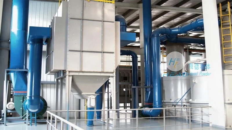
As we move into 2026, several technological developments are reshaping pneumatic conveying for fine powders. The integration of Industry 4.0 concepts is accelerating: smart conveying systems equipped with IoT sensors transmit real-time data on air consumption, pipe wall thickness (using ultrasonic sensors), and material mass flow to cloud-based platforms. Machine learning algorithms analyze historical data to predict blockages before they occur, schedule predictive maintenance, and optimize air-to-material ratios. For example, a recent installation at a high-performance concrete admixture plant in Europe uses a digital twin of the pneumatic conveying system to simulate different operating scenarios, achieving a 12% reduction in energy use within the first year. Another trend is the use of low-pressure dense phase conveying (LPDP), which employs pressures of only 2–3 bar but with specially designed fluidizing blow tanks that can handle silica fume at solid-to-air ratios above 60:1. LPDP systems reduce compressor capital cost and noise levels while maintaining the wear benefits of dense phase. Also gaining traction are modular, pre-engineered conveying skids that integrate blow tank, valves, controls, and filters on a single frame. These skids reduce installation time and commissioning risk, and are particularly attractive for smaller plants or retrofits. On the material handling front, "super-densified" silica fume (bulk density 650–750 kg/m³) is becoming more common as producers improve compaction processes; this material behaves less aeratably and may require slightly higher conveying velocities or modified blow tank designs. Finally, sustainability drivers are pushing system designs toward lower carbon footprints: using solar or wind power to run compressors, recovering heat from compressed air for building heating, and selecting pipes with recycled content (such as basalt-lined steel) are all emerging practices. Headpowder has been at the forefront of these trends, with multiple projects in 2025 employing solar-assisted compressed air stations and achieving net-zero emissions for the conveying portion of silica fume handling operations.
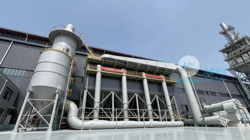
Designing and implementing a pneumatic conveying system for silica fume requires deep expertise in powder technology, fluid dynamics, and project management. Every plant has unique constraints: available footprint, existing utilities, required throughput, conveying distance, and material characteristics that may vary between suppliers. A one-size-fits-all approach almost always leads to operational issues—excessive wear, poor flow stability, or high energy bills. The most successful projects begin with a thorough material characterization (angle of repose, compressibility, permeability, aeration behavior, and wall friction) performed on your actual silica fume batch. This data feeds into a computational flow model that simulates pressure drops, slug formation, and velocity profiles for different pipe layouts. Next, a detailed energy analysis comparing dilute, dense, and vacuum options should be conducted, factoring in local electricity rates and maintenance labor costs. Finally, a phased commissioning plan with performance guarantees ensures that the system meets specified throughput, dust emission, and reliability targets. When evaluating potential suppliers, look for demonstrated experience in handling ultra-fine, abrasive powders similar to silica fume. Ask for references, performance data, and third-party test reports. The ability to provide turnkey service—including pipe fabrication, electrical, and control integration—reduces coordination risk. For companies exploring new installations or upgrades, engaging an expert early in the project cycle can yield substantial savings. Headpowder has delivered over 120 silica fume conveying systems worldwide, ranging from 2 t/h pilot lines to 30 t/h industrial units, serving cement, concrete, refractory, and ceramics sectors. To discuss your specific application or request a feasibility assessment, you can reach the team directly (咨询热线:156-6277-7102). Our engineers are available for site visits and can provide cost estimates for both conventional and advanced pneumatic conveying solutions tailored to silica fume.
Silica fume conveying is not a trivial engineering task—it demands an intimate understanding of material behavior, rigorous system design, and commitment to quality components. The three primary pneumatic conveying methods—dilute phase, dense phase (positive pressure), and vacuum—each offer distinct trade-offs between capital cost, energy efficiency, wear rate, and operational flexibility. For most new installations handling silica fume, dense phase conveying stands out as the optimal choice due to its lower energy consumption (typically 0.6–1.0 kWh per ton), minimal pipe wear (pipe life exceeding 5 years), and excellent material preservation. Dilute phase remains viable for short, low-capacity, or budget-constrained projects where simplicity is prioritized. Vacuum systems excel in dust-sensitive applications such as bulk truck unloading or multi-point feeding from open sources. Regardless of the method selected, investing in proper pipe bends, high-efficiency filters, smart instrumentation, and robust blow tanks pays for itself through reduced downtime and lower maintenance costs. As the construction and infrastructure sectors continue to grow, the global demand for silica fume is projected to reach 4.5 million tons by 2028, making efficient conveying systems more critical than ever. By applying the technical principles outlined in this article—from velocity selection to booster placement, from material testing to safety compliance—plant operators can achieve reliable, cost-effective, and environmentally responsible silica fume handling. The future of pneumatic conveying is smarter, greener, and more data-driven, and early adopters of these innovations will gain a competitive edge. Whether you are evaluating a new greenfield facility or optimizing an existing line, robust engineering and quality equipment are the foundation of success.

 Shandong headpowder Engineering Co., Ltd.
 156-6277-7102(Manager Zhang)
  0531-83386006
  Jinan City, Shandong Province, China
服务热线
微信咨询
回到顶部