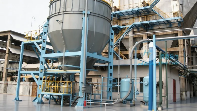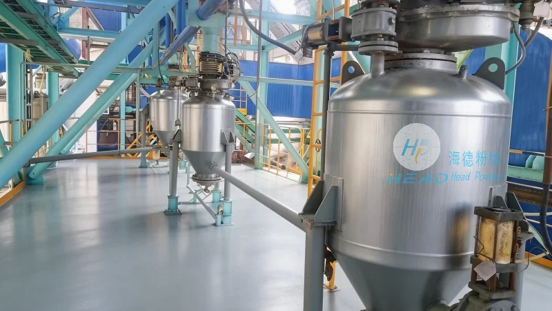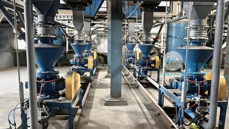

With over a decade of experience in the pneumatic conveying industry, our company specializes in a full range of pneumatic conveying system equipment.
您的当前位置:首页 >> News >> Technical FAQ

News

Rich project cases across industries, showing real implementation and proven technical strength.

Carbon Fiber Conveying: Pneumatic Guide

2026-07-08

Understanding Carbon Fiber Conveying: The Pneumatic Guide for Modern Manufacturing

Carbon fiber has become a cornerstone material in industries ranging from aerospace and automotive to wind energy and sporting goods. Its exceptional strength-to-weight ratio and stiffness make it indispensable for lightweight structural components. However, the process of handling and transporting carbon fiber materials—especially in powder, short fiber, or pellet forms—presents unique challenges. Conventional mechanical conveying systems often lead to fiber breakage, dust generation, and contamination, which degrade the material’s mechanical properties and increase production costs. This is where pneumatic conveying emerges as a preferred solution. Pneumatic systems use air pressure or vacuum to transport carbon fiber particles through enclosed pipelines, offering gentle handling, minimal degradation, and precise control over flow rates. This article provides a comprehensive, technical guide to carbon fiber pneumatic conveying, covering system types, design parameters, material behavior, operational considerations, and industry best practices. Whether you are a process engineer, a plant manager, or a procurement specialist, understanding these fundamentals will help you optimize your carbon fiber handling operations while maintaining product quality and reducing downtime. The insights shared are based on real-world applications and current industry data through 2026, ensuring relevance for today’s manufacturing environment.

Why Pneumatic Conveying for Carbon Fiber?

Carbon fiber particles are inherently fragile. Long fibers can break under mechanical stress, while short fibers and powders can agglomerate or become airborne, creating safety and quality risks. Pneumatic conveying addresses these issues by using a controlled air stream rather than mechanical parts like belts, screws, or buckets. This eliminates direct contact with moving machinery, significantly reducing fiber attrition. Additionally, enclosed systems prevent contamination from external sources and contain fugitive dust, which is critical for compliance with occupational safety standards. According to a 2025 market analysis, the global carbon fiber market is projected to exceed USD 8 billion by 2027, with a compound annual growth rate of over 10%. As production scales up, efficient material handling becomes a competitive differentiator. Companies that adopt optimized pneumatic conveying can achieve conveying rates of 500 kg/h to over 5,000 kg/h, depending on system design, while maintaining fiber length retention above 95% in many configurations. This makes pneumatic systems not just a technical choice but a strategic investment for any carbon fiber processing facility.

Key Design Parameters for Carbon Fiber Pneumatic Systems

Designing a pneumatic conveying system for carbon fiber requires careful consideration of several critical parameters. Unlike bulk materials such as sand or cement, carbon fiber exhibits low bulk density (often 0.1–0.5 g/cm³), high aspect ratio, and electrostatic charging tendencies. These characteristics influence every aspect of system design.

Material Properties and Flow Behavior

The first step is characterizing the carbon fiber feedstock. Powdered carbon fiber typically has particle sizes ranging from 10 to 200 microns, while milled fibers can be 50–500 microns in length. Chopped fibers (1–12 mm) are also common. The angle of repose, compressibility, and permeability determine how easily the material fluidizes. Carbon fiber tends to interlock due to its fibrous shape, which can cause bridging in hoppers and pipelines. To mitigate this, aeration pads or mechanical agitators are often installed at the material discharge point. The moisture content should also be controlled; even low humidity (below 0.5%) can affect flowability and static charge buildup. For optimal performance, the conveying line velocity must be carefully selected. Too low a velocity leads to settling and blockages; too high a velocity causes fiber breakage and energy waste. Typical conveying velocities for carbon fiber range from 8 to 20 m/s depending on particle size and system type.

System Types: Dilute Phase vs. Dense Phase

Two primary pneumatic conveying modes exist for carbon fiber: dilute phase and dense phase. Dilute phase systems suspend particles in a high-velocity air stream, typically at velocities above 15 m/s. They are suitable for shorter distances (up to 100 meters) and lower throughputs. However, the higher impact forces can increase fiber breakage. Dense phase conveying operates at lower velocities (2–8 m/s) and higher material-to-air ratios, moving material as a compact plug or slug. This gentler mode is preferred for fragile carbon fiber products, especially longer fibers, because it reduces degradation by up to 60% compared to dilute phase. The trade-off is a more complex system requiring higher inlet pressure and careful control of air injection points. Modern dense phase systems often incorporate pressure tanks, blow tanks, or rotary valves with variable frequency drives to adjust feed rates in real time. For high-value carbon fiber materials, the incremental investment in dense phase technology pays for itself through reduced waste and improved product consistency.

Pipeline Material and Layout Considerations

The conveying pipeline must be abrasion-resistant and electrically conductive to dissipate static charges. Stainless steel (304 or 316) is standard due to its corrosion resistance and smooth interior finish, which minimizes fiber buildup. Bends should have a radius of at least 6–8 times the pipe diameter to reduce impingement and fiber breakage. Long-radius bends or sweeping elbows are preferable to standard 90-degree turns. Additionally, grounding straps and anti-static liners are essential to prevent electrostatic discharge, which can damage electronics or create fire hazards. Pipeline diameter is selected based on the required conveying rate and pressure drop. For a typical carbon fiber line conveying 1,000 kg/h over 50 meters, an 80–100 mm diameter pipe is common. Computational fluid dynamics (CFD) simulations are increasingly used by experienced suppliers like headpowder to optimize pipe routing and minimize pressure losses before installation.

Operational Best Practices and Maintenance

Even the best-designed pneumatic system requires disciplined operation and regular maintenance to deliver consistent performance. Operators should monitor key parameters including air velocity, pressure differential, material flow rate, and temperature. Modern systems equipped with industrial IoT sensors provide real-time data that can be used for predictive maintenance. For example, a sudden increase in line pressure might indicate a partial blockage or filter clogging, prompting immediate action before a full shutdown occurs. Daily visual inspections of pipeline joints, valve seals, and filter bags are recommended. Carbon fiber dust is conductive and can accumulate on electrical components, so periodic cleaning of control panels and sensors is necessary. The air compressor or blower should be sized to deliver clean, dry air; moisture separators and coalescing filters are standard accessories. Headpowder recommends scheduling a comprehensive system audit at least twice per year, including wear measurements on bends and diverter valves, to extend equipment life and maintain conveying efficiency above 90%.

Addressing Common Challenges in Carbon Fiber Conveying

Fiber Breakage and Attrition Control

Minimizing fiber breakage is the top priority for most carbon fiber processors. Studies from 2024 indicate that improper conveying can reduce fiber length by 20–40% compared to the original feedstock, directly impacting the mechanical properties of molded parts. Solutions include using soft-start valves to prevent sudden air bursts, avoiding sharp bends, and employing venturi-style feeders instead of rotary airlocks for longer fibers. Some advanced systems incorporate a bypass air injection at the feeder outlet to accelerate the material gradually rather than abruptly. In practice, headpowder’s dense phase systems have demonstrated fiber length retention rates exceeding 97% for milled carbon fiber with an initial length of 150 microns, based on third-party validation at a European aerospace composites facility. This level of performance directly translates into lower raw material costs (less waste) and higher final product strength.

Static Electricity and Dust Explosion Risks

Carbon fiber dust is not only conductive but also combustible under certain conditions. The NFPA 654 standard for combustible particulate solids applies, requiring proper grounding, bonding, and explosion relief panels in enclosed systems. The minimum ignition energy for carbon fiber dust is around 10–100 mJ, similar to many metal powders. To mitigate risks, all conveying components must be grounded with resistance to ground less than 10 ohms. Explosion venting or suppression systems should be incorporated in hoppers and filter receivers. Additionally, inert gas blanketing (e.g., nitrogen) can be used in closed-loop systems processing fine carbon fiber powders. Compliance with OSHA and local regulations is mandatory, and regular hazard analysis (such as DHA per NFPA 652) is recommended. Headpowder provides custom safety integration as part of its pneumatic system packages, including certified grounding kits and explosion-vent panels tailored to carbon fiber applications.

Material Segregation and Agglomeration

When conveying blends of different fiber lengths or mixed with other additives, segregation can occur due to differences in particle size and density. This is particularly problematic for formulation consistency in injection molding or compression molding processes. To counteract segregation, headpowder recommends using a homogeneous feed hopper with live-bottom stirring and maintaining a steady air-to-material ratio throughout the line. In dense phase systems, the plug flow regime naturally reduces segregation because the material moves as a cohesive slug. Post-conveying sampling and analysis should be performed periodically to verify that the blend composition matches the target specification.

Selecting the Right Pneumatic Conveying System: A Practical Framework

Choosing between dilute phase, dense phase, or a hybrid system depends on multiple factors: material form (powder, milled, chopped), conveying distance, required throughput, acceptable degradation, and available floor space. Below is a simplified decision matrix based on industry data through early 2026:

  • Milled carbon fiber (50–200 µm): dilute phase is usually sufficient for distances under 80 m and throughputs under 2,000 kg/h. Degradation is typically below 10%.
  • Chopped carbon fiber (3–12 mm): dense phase is strongly recommended to preserve fiber length. Throughput of 500–3,000 kg/h is achievable with proper blow tank design.
  • Carbon fiber powder (fine <50 µm): dilute phase with low velocity (10–12 m/s) and anti-static coating works well. Special care is needed for dust containment.
  • Long distances (>100 m): dense phase or a combination of dense phase with intermediate booster pumps becomes necessary to maintain material integrity.

For most commercial carbon fiber compounding plants, a modular dense phase system from headpowder offers the best balance of reliability and cost efficiency. One example is a North American automotive parts manufacturer that replaced a mechanical bucket elevator with a headpowder pneumatic conveying line, achieving a 35% reduction in fiber breakage and a 20% increase in overall equipment effectiveness within the first month of operation. Such results underscore the importance of partnering with a supplier who understands the unique rheology of carbon fiber materials.

Integration with Downstream Processes and Automation

Carbon Fiber Conveying: Pneumatic Guide

Modern carbon fiber production lines rarely operate in isolation. Pneumatic conveying systems must interface seamlessly with feeders, mixers, extruders, or presses. Close collaboration between the conveying system designer and the process engineer is essential. For example, when feeding a twin-screw extruder, the conveying rate must be precisely synchronized with the extruder’s screw speed to avoid starve feeding or flooding. Headpowder’s control systems include PLC-based automation with PROFIBUS or Ethernet/IP communication, allowing real‑time recipe management and data logging. A well-integrated system also enables quick changeovers between different carbon fiber grades, reducing downtime by up to 40%. The trend toward Industry 4.0 in 2025–2026 has pushed many processors to demand remote monitoring capabilities. Headpowder’s pneumatic solutions offer cloud-based dashboards that track conveying efficiency, material consumption, and predictive alerts, which can be accessed via tablet or smartphone. This level of digital integration not only improves operational visibility but also supports continuous improvement initiatives.

Future Trends in Carbon Fiber Pneumatic Conveying

Carbon Fiber Conveying: Pneumatic Guide

The carbon fiber market is expected to see increased demand from next‑generation applications such as hydrogen storage tanks, urban air mobility vehicles, and recycled carbon fiber. Recycled carbon fiber, often recovered from pyrolysis or solvolysis, presents additional challenges due to shorter fiber lengths and variable surface chemistry. Pneumatic conveying systems designed for recycled feedstocks must accommodate wider particle size distributions and higher impurity levels. Research published in 2025 indicates that combining dense phase conveying with online particle size measurement (using laser diffraction) can improve process stability by 18%. Additionally, advances in wear‑resistant ceramic linings for pipeline bends are extending maintenance intervals from months to years. The use of artificial intelligence for self‑optimizing conveying parameters is also emerging, with pilot projects demonstrating 12–15% energy savings while preserving material quality. For processors looking to stay competitive, investing in a modern pneumatic system today provides a foundation that can adapt to these evolving requirements without major retrofits.

Conclusion: Partnering for Pneumatic Excellence

Carbon Fiber Conveying: Pneumatic Guide

Effective carbon fiber conveying through pneumatic systems is not a one‑size‑fits‑all proposition. It requires deep knowledge of material science, fluid dynamics, and process automation. Whether you are scaling up a laboratory process to full production or retrofitting an existing facility to improve quality, the right pneumatic solution can deliver measurable gains in fiber integrity, throughput, and safety. As the industry moves toward higher performance standards and tighter sustainability targets, the importance of reliable, gentle, and efficient material handling will only grow. Companies like headpowder, with years of hands‑on experience in pneumatic conveying for advanced materials, provide not only equipment but also engineering services, commissioning support, and after‑sales care (consulting hotline: 156-6277-7102). By partnering with specialists who treat your carbon fiber products with the care they demand, you can reduce operational risks, improve product consistency, and ultimately strengthen your market position. The information presented here serves as a foundational guide for evaluating your conveying needs and initiating informed discussions with technology providers. Remember that every carbon fiber application has its own nuances; a thorough on‑site analysis and pilot testing are recommended before full system commitment. With careful planning and the right pneumatic conveying strategy, your carbon fiber processing line can achieve new levels of performance and profitability.

相关推荐

Shandong headpowder Engineering Co., Ltd. All rights reserved.

回到顶部