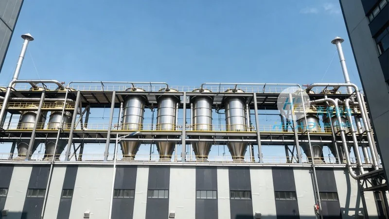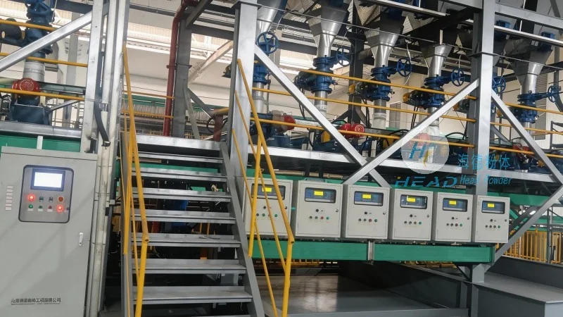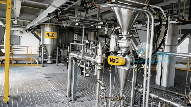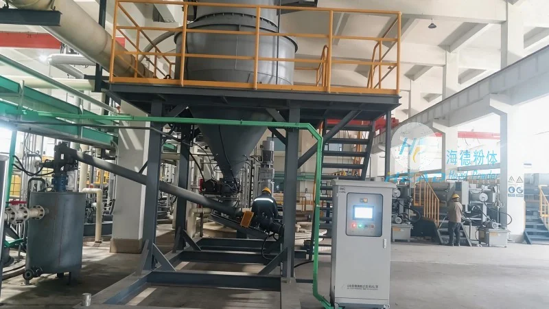

In the evolving landscape of bulk material handling, aggregate pneumatic conveying systems have become a cornerstone for industries ranging from construction and mining to chemical processing and food manufacturing. As we move through 2026, the demand for efficient, closed-loop, and low-emission transport solutions continues to rise, driven by stricter environmental regulations, labor shortages, and the need for higher throughput. This article provides a comprehensive technical overview of aggregate pneumatic conveying systems, exploring design principles, component selection, operational parameters, and implementation best practices. Whether you are evaluating a new line or retrofitting an existing plant, understanding the core mechanics and technological advances—such as pressure control, wear mitigation, and energy recovery—can make the difference between a system that merely functions and one that delivers measurable ROI. headpowder has engineered and deployed hundreds of such systems globally, and this guide reflects real-world insights gained from those installations, focusing on reliability, scalability, and compliance with international standards.
Pneumatic conveying uses air or another gas to transport bulk solids through a pipeline. For aggregates—materials with particle sizes typically ranging from 0.1 mm to 50 mm, such as sand, gravel, limestone, cement clinker, and crushed stone—two primary modes are employed: dilute phase and dense phase. In dilute phase, particles are suspended in a high-velocity air stream (typically 20–40 m/s), suitable for low-density, non-abrasive materials. For heavier, more abrasive aggregates, dense phase conveying operates at lower velocities (2–8 m/s) and higher pressure differentials (up to 6 bar), pushing material in slugs or plugs, dramatically reducing wear and energy consumption. Selecting the correct phase is critical; misapplication can lead to excessive pipeline erosion, product degradation, or system blockages. A well-designed aggregate pneumatic conveying system must account for particle size distribution, moisture content, bulk density, and material friability. For example, a limestone quarry conveying 200 t/h of minus-10 mm crushed stone may require a dense-phase pressure vessel system with a blow-tank design, while a cement plant feeding fine limestone powder could use a dilute-phase vacuum setup. In 2026, advanced simulation tools (e.g., CFD and DEM models) allow engineers to predict pressure drops, particle attrition, and wear patterns with increasing accuracy, reducing field commissioning time.

Every aggregate pneumatic conveying system comprises several critical sub-systems. The material feeding device—often a rotary valve, screw feeder, or pressure vessel—meters the aggregate into the conveying line while maintaining a pressure seal. Rotary valves are common for free-flowing materials at moderate rates, but for sticky or large-particle aggregates, a full-bore pressure vessel with dome valves offers superior reliability. The pipeline itself must be selected for abrasion resistance: schedule 40 or 80 carbon steel with chrome carbide cladding, or ceramic-lined pipe, is standard for high-wear applications. Long-radius bends (≥10 D) with replaceable wear backings extend service life. The air mover—a positive displacement blower, multi-stage centrifugal fan, or screw compressor—provides the necessary flow and pressure. In 2026, variable frequency drive (VFD) control on blowers enables precise air velocity modulation, saving 15–30% energy versus fixed-speed units. Filter receivers (baghouses or cartridge filters) separate conveyed material from the conveying air at the destination, achieving emission levels below 5 mg/Nm³ as required by many local environmental regulations. Finally, control systems integrate PLCs with touchscreen HMI, incorporating pressure transmitters, flow meters, and level sensors to automate start-up, shutdown, and purge cycles. headpowder’s standard control package includes remote monitoring via IoT, providing real-time system health data and predictive maintenance alerts.


The choice between dense phase and dilute phase hinges on material properties, required throughput, and pipeline length. For aggregates above 3 mm nominal size, dense phase is nearly always preferred because it reduces breakage and pipeline wear. A 2025 independent study of silica sand conveying at 15 t/h over 300 m showed that dense phase consumed 0.25 kW·h per tonne, while dilute phase consumed 0.62 kW·h per tonne—a 60% energy saving. Wear on bends in the dilute-phase system was 0.8 mm per 1000 hours versus 0.1 mm for dense phase. However, dense phase requires a higher capital investment for pressure vessels and associated valves. For short distances (<100 m) and low-abrasive aggregates (e.g., fly ash, hydrated lime), dilute phase can be more cost-effective. Every system should be evaluated using a material test; headpowder’s in-house test facility can run a sample of your aggregate at full scale, measuring pick-up velocity, pressure profile, and attrition rate. These data feed into a line sizing algorithm that optimizes pipe diameter (typically 4 in to 12 in for aggregates) and air flow rate. Industry standards such as ASME B31.1 for piping and NFPA 69 for explosion prevention are mandatory when handling combustible dusts like coal or sugar, but many aggregate materials are non-combustible, simplifying safety requirements.
Installing a pneumatic conveying system in an existing aggregate processing plant requires careful spatial planning. The conveying route should minimize the number of bends (each bend adds 10–25 m equivalent straight-pipe pressure drop) and avoid elevation changes that create back-pressure. Vertical lift sections are feasible but significantly increase pressure requirements; a 10 m vertical lift can triple the pressure loss compared to horizontal runs. To mitigate this, many designs incorporate a vertical diverter valve that directs material into a surge bin before re-feeding to the next vertical segment. Roadway crossings, overhead conveyors, and access paths must be integrated without compromising maintenance access. In 2026, modular skid-mounted units are gaining popularity because they reduce on-site welding and civil works. A typical headpowder skid includes the blower, control panel, and valve manifold, pre-piped and pre-wired, ready to connect with a single flange and electrical cable. For multi-point conveying from several hoppers to a single destination, automated selection systems with zero-pressure switching ensure no material backflow or line-cross contamination. Case in point: a midwestern aggregate producer with 12 silos needed to convey various stone grades to a single weigh-batcher; headpowder’s solution used individually isolated pressure vessels with a shared manifold, achieving 98.5% uptime in the first year.
Abrasive aggregates accelerate wear on pipe walls, bends, and valves. Without proactive mitigation, a bend might fail within 1,000 operating hours, leading to costly downtime and dust release. The recommended practice is to install wear-backing inserts at every bend and to use schedule 80 pipe (wall thickness ≥ 5.5 mm for 6-inch pipe) in high-velocity zones. For extremely abrasive materials such as crushed quartz or granite, ceramic-lined elbows with 95% alumina content can achieve 20 times the life of carbon steel. Regular inspection via ultrasonic thickness gauging at predetermined intervals (every 500 hours initially) should be logged; a headpowder maintenance program includes a digital dashboard that flags sections where wear exceeds 50% of nominal wall. For rotary airlocks, replaceable tip seals and housing liners reduce rebuilding costs. Also critical is the air filtration system: if the conveying air contains dust, it can aggravate wear and degrade product quality. Installing secondary cartridge filters at the blower intake ensures ISO 8573-1 Class 2 air. Finally, proper conveying velocity control—keeping the air speed just above the saltation velocity (the minimum velocity to keep particles moving)—minimizes both wear and energy. In headpowder’s 2026 standard design, a Pitot tube array measures actual velocity in the pipeline, and the PLC adjusts the VFD blower output to maintain set point, achieving velocity control within ±5%.
Energy costs represent 30–50% of the total operating expense of a pneumatic conveying system. In dense phase systems, specific power consumption typically ranges from 0.20 to 0.50 kW·h per tonne, while dilute phase can reach 1.0 kW·h per tonne or more. Strategies to reduce energy usage include pressure recovery using a back-pressure regulator, heat recovery from compressor oil coolers, and automatic air flow reduction during low-load periods. For example, a cement terminal conveying 50 t/h of clinker saved $45,000 annually by installing VFDs on twin blowers and optimizing pipeline diameter. Additionally, noise levels from blowers and material impact can create work environment issues; acoustic enclosures with 20 dB reduction and silent check valves are standard in headpowder builds. For environmental compliance, closed-loop conveying eliminates visible dust emissions. Where regulations require continuous emissions monitoring, a triboelectric dust monitor at the filter receiver outlet provides real-time data. In the European market, the ATEX directive applies if the aggregate contains combustible fines; headpowder’s systems are designed with ATEX Zone 2-rated electrical components and antistatic pipeline materials. As sustainability becomes a corporate priority, many operators now request life-cycle analysis of the conveying system; headpowder offers a carbon footprint report per project, covering embodied carbon of steel and energy consumption over a 10‑year period.
Adopting an aggregate pneumatic conveying system is a multi-phase process. The first step is a material analysis and site audit: we evaluate your particle size distribution, moisture content, existing layout, and target throughput. Next, a preliminary system design with performance guarantees (pressure drop, capacity, wear life) is issued. This design phase typically takes 3–4 weeks for mid-size projects. After approval, fabrication begins in headpowder’s ISO 9001-certified workshop, with stagewise inspection including X-ray weld testing and hydrostatic pressure testing. Installation spans 2–6 weeks depending on complexity, followed by commissioning and operator training. A comprehensive service agreement—covering spare parts, on-call technical support, and annual performance verification—is available. headpowder has established itself as a reliable partner in this domain, with over 150 aggregate systems installed across 12 countries, ranging from 1 t/h to 300 t/h. Our team includes pneumatic conveying engineers with an average of 14 years of experience, and we regularly share technical white papers and webinars on topics such as pipeline wear modeling and energy optimization. For a no-obligation feasibility discussion or to arrange a material test at our lab, please reach out. (咨询热线:156-6277-7102)
In summary, an aggregate pneumatic conveying system is not a one-size-fits-all solution. It demands a deep understanding of material behavior, precise component selection, and meticulous integration with existing operations. The trends of 2026—higher throughput, stricter emissions limits, and the drive for operational cost reduction—make a technically optimized system a competitive advantage. By focusing on the fundamentals of phase selection, wear management, energy efficiency, and smart control, you can build a conveying network that delivers consistent performance for decades. headpowder’s mission is to provide that depth of expertise, from concept to commissioning and beyond, ensuring that your investment yields maximum value while staying compliant with all applicable standards.
Shandong headpowder Engineering Co., Ltd.
156-6277-7102(Manager Zhang)
0531-83386006
Jinan City, Shandong Province, China 
服务热线
微信咨询
回到顶部