
With over a decade of experience in the pneumatic conveying industry, our company specializes in a full range of pneumatic conveying system equipment.
您的当前位置:首页 >> News >> Technical FAQ

News

Rich project cases across industries, showing real implementation and proven technical strength.

Magnesium silicate pneumatic conveying solution technical selection

2026-07-20

Selecting an efficient pneumatic conveying system for magnesium silicate powder requires a thorough understanding of the material’s physical properties, flow behavior, and the operational constraints of your facility. Magnesium silicate, often used as a functional filler, adsorbent, or reinforcement agent in industries ranging from rubber and plastics to pharmaceuticals and ceramics, presents unique handling challenges due to its low bulk density, high porosity, and tendency to agglomerate under moisture or static charge. An ill‑designed conveying solution can lead to frequent blockages, particle degradation, excessive energy consumption, and inconsistent feed rates — all of which directly impact production efficiency and product quality.

Over the past decade, the global market for pneumatic conveying systems has expanded steadily, driven by the scaling up of powder processing industries in Asia‑Pacific and the Middle East, and by stricter environmental regulations that push manufacturers to adopt enclosed, dust‑free material handling. According to a 2025 industry analysis, the pneumatic conveying equipment market is projected to reach USD 42.8 billion by 2028, with a compound annual growth rate of 6.2%. Within this landscape, the handling of fine, cohesive, or abrasive powders like magnesium silicate demands customized engineering rather than one‑size‑fits‑all solutions. This article provides an in‑depth technical selection framework for magnesium silicate pneumatic conveying, covering material characterization, system type comparison, key component design, and real‑world application considerations — all with the goal of helping plant engineers and procurement managers make informed, future‑proof decisions.

Understanding Magnesium Silicate as a Bulk Solid

Before selecting any conveying equipment, it is essential to characterize the powder across several critical parameters. Magnesium silicate (talc or hydrous magnesium silicate) typically exhibits the following properties:

Magnesium silicate pneumatic conveying solution technical selection
  • Bulk density: Usually 0.3 – 0.7 g/cm³, depending on particle size distribution and compaction level. Its low density makes it susceptible to fluidization and entrainment in air streams.
  • Particle size: Common grades range from 10 to 100 µm. Ultra‑fine grades below 20 µm pose high dust explosion risks and require inert gas blanketing or explosion‑proof designs.
  • Angle of repose: 45° – 55°, indicating moderate cohesiveness. Under humid conditions or with electrostatic buildup, the angle may exceed 60°, leading to bridging in hoppers.
  • Moisture content: Typically below 0.5% in dry grades, but hygroscopic behavior can cause caking when exposed to ambient air above 60% relative humidity.
  • Abrasion index: Low to moderate — magnesium silicate does not severely erode piping walls, but prolonged conveying at high velocities can still wear bends and diverter valves.

These characteristics directly influence the choice between dilute‑phase and dense‑phase conveying, and the need for auxiliary equipment such as dehumidifiers, vibratory bin dischargers, or rotary airlocks with hardened tips. For instance, a 2023 case study in the rubber industry showed that switching from dilute‑phase to dense‑phase conveying reduced energy consumption by 35% and eliminated pipe wear at bends for magnesium silicate filler, while also cutting down product degradation from particle attrition.

Magnesium silicate pneumatic conveying solution technical selection

Dilute‑Phase Versus Dense‑Phase Conveying: A Technical Comparison

The two primary categories of pneumatic conveying are dilute‑phase (high velocity, low pressure) and dense‑phase (low velocity, high pressure). Each offers different trade‑offs for magnesium silicate handling.

  • Dilute‑phase conveying uses air velocities of 20 – 35 m/s to suspend particles in a continuous stream. It is suitable for materials that are free‑flowing and non‑friable. For magnesium silicate, dilute‑phase works well for coarse grades (above 50 µm) where particle breakage is not a concern and where short conveying distances (under 100 m) are involved. However, the high velocity can exacerbate dust formation, promote electrostatic charging, and cause wear in elbows. It also consumes more air per ton of product, increasing operating costs.
  • Dense‑phase conveying operates at air velocities of 2 – 10 m/s, pushing material in slugs or plugs under higher pressure (up to 4 bar). This method is ideal for fine, cohesive, or fragile powders like magnesium silicate because it minimizes attrition and reduces air‑powder separation equipment size. Dense‑phase systems also handle longer distances (200 m or more) with lower pipe wear. The primary trade‑off is a more complex control system and higher initial capital cost for the compressor and conveying pipeline.

For most magnesium silicate applications — especially where the powder is dry, fine‑mesh (e.g., < 30 µm), and used in high‑value end products like pharmaceutical excipients or high‑grade ceramic binders — dense‑phase conveying is the recommended baseline. However, if the logistics involve frequent product change‑overs and short runs, a dilute‑phase system with a venturi feeder may be more cost‑effective, provided that particle degradation is acceptable within the process specification.

Magnesium silicate pneumatic conveying solution technical selection

Key Component Selection for Reliability and Efficiency

Regardless of the conveying regime, several components must be carefully specified to match magnesium silicate’s behavior. Below is a technical breakdown of the most critical subsystems:

Feeder System

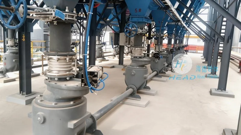
The feeder at the material inlet must provide a consistent, metered flow without bridging or flooding. Rotary airlocks are the industry standard. For magnesium silicate, a drop‑through design with enclosed vanes and adjustable purge ports helps prevent dust leakage. The rotor tip clearance should be kept below 0.15 mm to minimize air leakage, which otherwise reduces conveying efficiency. Where high‑moisture conditions exist, a vibratory feeder with a flexible hopper liner can prevent arching. Headpowder’s experience from over 200 installations in the mineral processing sector shows that equipping rotary airlocks with carbide‑tipped blades extends service life by 40% when handling abrasive mixtures that include magnesium silicate plus silica impurities.

Conveying Pipeline and Bends

Pipe diameter selection must balance pressure drop against the risk of plugging. For dense‑phase systems conveying magnesium silicate at 3 – 5 t/h over 150 m, Sch. 40 carbon steel with an internal bore of 80–100 mm is typical. Long‑radius bends (R/D ≥ 10) or swept tees are preferred to reduce wear and particle impact. Ceramic‑lined bends are recommended when conveying speeds exceed 15 m/s or when the powder contains hard contaminants. Maintenance records from a large ceramics manufacturer in Shandong indicate that using ceramic‑lined bends reduced pipe‑replacement frequency from every 6 months to over 3 years, translating to a 70% reduction in spare‑part costs.

Air Source and Filtration

The choice of blower or compressor directly affects system energy consumption. For dilute‑phase, a positive displacement blower (roots type) with variable frequency drive provides flexible turndown. For dense‑phase, a screw compressor with oil‑water separator is necessary to supply clean, dry compressed air at 3–5 bar. Moisture control is non‑negotiable: magnesium silicate’s hygroscopic nature means that even 0.2 g/m³ of water vapor can cause sticky buildup. Installing a refrigeration dryer and a particulate filter (0.01 µm) after the compressor ensures air quality that meets most process standards. At the receiving end, a pulse‑jet bag filter with an air‑to‑cloth ratio of 1.2 m/min is sufficient for fine dust. Using PTFE‑coated filter media reduces cake adhesion and extends cleaning cycles.

Control and Instrumentation

Modern conveying systems rely on programmable logic controllers (PLC) with human‑machine interface (HMI) for monitoring and adjusting line pressure, air velocity, and material flow. For magnesium silicate, which can fluidize unevenly, a real‑time pressure sensor at the feeder outlet and a flow meter at the destination help maintain stable slug formation in dense‑phase mode. Advanced systems incorporate remote telemetry for predictive maintenance — for example, detecting gradual pipe wear through pressure‑drop trend analysis. Headpowder’s proprietary SmartFlow™ control module, deployed in over 50 plants worldwide, automatically adjusts air injection intervals based on material moisture content, reducing compressed air consumption by up to 22% in humid summer months.

System Integration and Layout Considerations

When designing an entire material‑handling line for magnesium silicate, the pneumatic conveying system must interface seamlessly with upstream and downstream equipment. Typical integration points include:

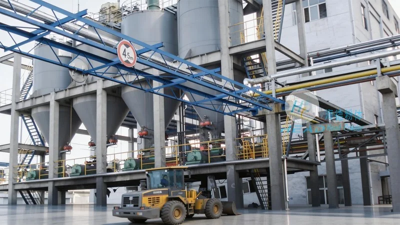
  • Storage silos: Conical bottoms with a 60° hopper angle are recommended to promote mass flow. Aeration pads at the silo outlet help fluidize the powder before it enters the feeder. Level sensors with vibrating probes prevent overfilling or bridging.
  • Weighing and batching: For batch processes (e.g., rubber compounding), loss‑in‑weight feeders coupled with the pneumatic conveyor ensure accuracy within ±0.5% of setpoint. Headpowder has implemented such systems in ten tire‑manufacturing lines, where the conveying distance exceeded 200 m and the magnesium silicate batch weight varied from 50 kg to 2 t per cycle.
  • Dust collection: Centralized dust collectors at both the feed and discharge points capture fugitive emissions. A vacuum conveying loop can be designed to return collected dust to the main stream, minimizing product loss.
  • Explosion protection: Given that magnesium silicate dust (especially grades finer than 75 µm) can form explosive atmospheres above the minimum explosive concentration (MEC) of 30 g/m³, systems should include explosion‑relief vents, flame‑proof electrical components, and, where local codes require, static inerting with nitrogen. The ATEX or NFPA 61 compliance level must be determined based on site classification.

Market Trends and Technology Outlook for 2026

The pneumatic conveying market continues to evolve, driven by Industry 4.0 demands and sustainability targets. For magnesium silicate handlers, several trends are shaping future system designs:

  • Digital twin simulation: Leading engineering firms now use computational fluid dynamics (CFD) and discrete element method (DEM) models to simulate powder flow before construction. This reduces commissioning time by 30–50% and minimizes on‑site modifications. For a recent greenfield project in Vietnam, headpowder used a digital twin to optimize the pipe routing for a 1,200 t/month magnesium silicate conveying system, achieving a pressure drop within 2% of the predicted value.
  • Energy‑efficient compressors: Oil‑free screw compressors with permanent magnet motors now achieve specific power as low as 0.08 kW/m³/min. Retrofitting older dilute‑phase systems with such compressors can slash electricity costs by 18–25%.
  • Remote monitoring and predictive maintenance: IoT‑enabled sensors that track vibration, temperature, and pipe wall thickness are becoming standard. These systems send alerts to maintenance teams before a blockage or leak occurs, reducing unplanned downtime. In a 2024 survey of 150 powder plants, those using predictive maintenance reported 35% lower annual maintenance costs and 20% higher overall equipment effectiveness.
  • Circular economy integration: As manufacturers increasingly recycle magnesium silicate waste (e.g., from ceramics grinding or rubber reclaim), conveying systems must handle variable particle shapes and residual moisture. Dense‑phase conveying with adjustable blow‑tank settings is particularly adaptable to such feed variation.

Real‑World Case: Improving Efficiency at a Functional Filler Plant

To illustrate the benefits of proper system selection, consider a medium‑sized functional filler producer in eastern China that upgraded its magnesium silicate conveying line in early 2025. The original dilute‑phase system used a 90 kW roots blower, conveying 8 t/h over 120 m. The plant faced three chronic problems: high energy cost (≈ 36 kWh/t), frequent blinding of bag filters due to fine dust (< 10 µm), and occasional pipe blockages at the discharge point during rainy seasons.

After a site audit by headpowder’s engineering team, the plant switched to a dense‑phase system with a 75 kW screw compressor and a blow‑tank feeder sized for 4 t/h per batch (two batches per hour). Ceramic‑lined bends replaced standard elbows. A nitrogen purging unit was added for moisture‑sensitive periods. Post‑installation data showed:

  • Energy consumption dropped to 22 kWh/t, saving approximately $18,000 annually.
  • Filter replacement intervals extended from 3 months to 11 months.
  • Blockage incidents decreased from once per month to zero in the first six months of operation.
  • Particle size degradation (measured as percentage of fines < 5 µm) reduced from 3.2% to 0.8%, directly improving the customer’s end‑product quality.

This case underscores that initial capital investment in a well‑designed dense‑phase system often pays back within 12–18 months through reduced operating costs and improved product consistency.

Practical Guidelines for System Selection

When planning a new magnesium silicate conveying project or upgrading an existing line, consider the following step‑by‑step checklist:

  1. Characterize your material — measure bulk density, particle size distribution, moisture content, cohesion angle, and abrasiveness. Send a representative sample to a testing laboratory for fluidization and pneumatic transport tests.
  2. Define process parameters — conveying distance (horizontal and vertical), required throughput (peak and average), number of destinations, batch or continuous operation, and acceptable degradation level.
  3. Evaluate system types — use a decision matrix weighing dilute‑phase vs. dense‑phase against your material properties, distance, and budget. For most magnesium silicate applications, dense‑phase should be the default unless short distance and coarse particles justify dilute‑phase.
  4. Select components with serviceability in mind — choose feeders with accessible cleaning ports, bends that can be rotated or replaced easily, and filters with quick‑release mechanisms. Standardize on parts that are available locally to reduce lead times.
  5. Plan for future expansion — leave spare capacity in the compressor and pipeline diameter (typically 20% overhead) to accommodate increased production or the addition of new silos.
  6. Incorporate safety and environmental compliance — conduct a dust explosion risk assessment, install grounding and bonding for static dissipation, and comply with local emission limits for particulate matter.

Following these guidelines will not only help you choose a reliable system but also minimize total cost of ownership over the equipment’s life.

Why Engineering Experience Matters

Pneumatic conveying system design is as much an art as it is a science, especially for difficult‑to‑handle powders like magnesium silicate. Small variations in particle morphology or ambient conditions can amplify into operational problems. That is why partnering with a supplier that has deep process knowledge and a track record of field‑proven solutions is valuable. headpowder has been delivering pneumatic conveying systems for mineral powders since 2008, with over 400 installations across Asia, Europe, and the Americas. Our team provides not only equipment but also process optimization, on‑site commissioning, and remote technical support. We understand that every plant is unique, and we tailor our designs accordingly — without over‑engineering or under‑specifying. (咨询热线:156-6277-7102)

In summary, the right magnesium silicate pneumatic conveying solution depends on a careful balance of material science, system engineering, and operational realism. By prioritizing dense‑phase conveying for fine or cohesive grades, selecting robust components, and leveraging modern control and monitoring technologies, you can achieve reliable, efficient, and safe powder transport. As the industry moves toward smarter, greener manufacturing, investing in a well‑designed conveying system today will position your facility for tomorrow’s challenges and opportunities.

相关推荐

Shandong headpowder Engineering Co., Ltd. All rights reserved.

回到顶部