

High Temperature Fine Powder Pneumatic Conveying Technology: Principles, Applications, and Development Trends
High temperature fine powder pneumatic conveying technology is a critical process in modern industrial operations, particularly in sectors dealing with high-temperature and fine particulate materials. This technology involves the transport of fine powders through a pipeline using a gas stream, typically air or other suitable gases. The process is essential for efficient material handling, ensuring safe and reliable movement of materials that are often sensitive to temperature and moisture.
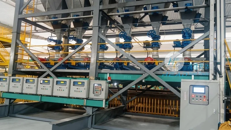
Principles of High Temperature Fine Powder Pneumatic Conveying
The core principle of high temperature fine powder pneumatic conveying is the use of a pressurized or vacuum system to move fine particles through a pipeline. In pressurized systems, a blower or compressor generates the necessary pressure to push the material through the line, while in vacuum systems, a vacuum pump creates a negative pressure to draw the material. The gas flow rate and pressure are carefully controlled to ensure that the fine particles are suspended and transported without clogging or degradation. The technology relies on the balance between the gas velocity and the particle size, density, and moisture content to maintain a stable conveying condition. For high temperature applications, specialized equipment such as high-temperature blowers, heat-resistant pipelines, and temperature sensors are employed to handle the elevated temperatures without compromising the system's integrity or performance.
Applications in Industrial Sectors
High temperature fine powder pneumatic conveying technology finds extensive applications across various industrial sectors. In the cement industry, it is used for transporting raw materials like limestone and clinker, which are often at high temperatures. The technology ensures efficient and safe handling of these materials, reducing the risk of dust explosions and improving overall production efficiency. In the chemical industry, it is employed for conveying fine powders such as pigments, catalysts, and specialty chemicals, which may be sensitive to temperature and moisture. The system's ability to maintain consistent temperature and pressure helps in preserving the quality of these materials during transport. Additionally, in the power generation sector, high temperature fine powder conveying is used for transporting fly ash from boilers, which is crucial for waste management and environmental compliance. The technology also plays a vital role in the pharmaceutical and food industries, where it is used for conveying fine powders that require strict temperature and contamination control.
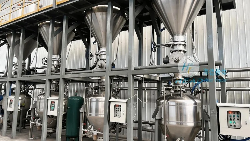
Key Components and System Design
The high temperature fine powder pneumatic conveying system consists of several key components that work in tandem to ensure efficient operation. These include the air supply system (blower or compressor), the conveying pipeline (typically made of stainless steel or other heat-resistant materials), the material feeders (such as rotary valves or screw feeders), and the control system (including pressure and temperature sensors). The air supply system is designed to handle high temperatures, with options like high-temperature centrifugal blowers or positive displacement blowers. The pipeline is often insulated to prevent heat loss and maintain the material's temperature during transport. The material feeders are critical for controlling the flow rate and preventing blockages, especially when dealing with fine powders that are prone to bridging. The control system monitors parameters such as pressure, temperature, and flow rate, ensuring that the system operates within safe and optimal conditions. The design of the system must also consider factors such as material properties, conveying distance, and required throughput to achieve the desired performance.
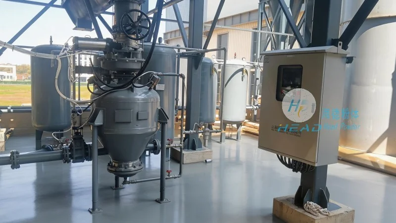
Advantages and Challenges
High temperature fine powder pneumatic conveying offers several advantages over traditional methods like belt conveyors or bucket elevators. One of the primary advantages is the ability to handle fine powders that are difficult to transport using conventional equipment. The system provides a dust-free and enclosed environment, reducing the risk of dust explosions and improving workplace safety. Additionally, it allows for precise control over the material flow rate and temperature, which is essential for maintaining product quality. The technology also enables the integration of multiple process steps, such as drying and conveying, into a single system, reducing the overall footprint and operational costs. However, the technology also presents several challenges. One of the main challenges is the handling of high temperatures, which requires specialized equipment and materials to prevent corrosion and wear. The system is also susceptible to clogging and blockages, especially when dealing with fine powders that have high moisture content or are prone to agglomeration. Another challenge is the energy consumption, as high temperature conveying systems require more power compared to conventional systems. Despite these challenges, the benefits of high temperature fine powder pneumatic conveying make it a preferred choice in many industrial applications.
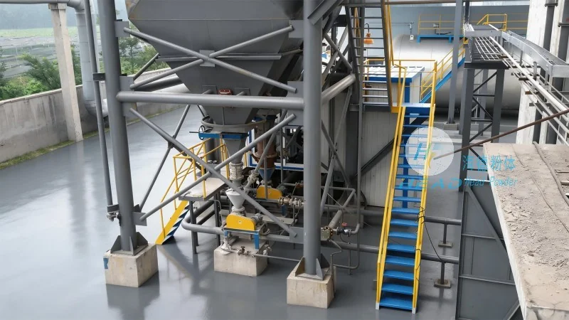
Development Trends and Future Outlook
The field of high temperature fine powder pneumatic conveying is continuously evolving, with several development trends shaping its future. One of the key trends is the integration of advanced control systems and automation. Modern systems now use sensors and control algorithms to optimize the conveying process, ensuring efficient operation and reducing energy consumption. The use of artificial intelligence and machine learning is also being explored to predict system performance and detect potential issues before they occur. Another trend is the development of more efficient and energy-saving equipment. Manufacturers are developing high-efficiency blowers and compressors that consume less power while maintaining the required pressure and flow rate. The use of heat recovery systems is also becoming more common, where the heat generated during the conveying process is recovered and used for other applications, improving overall energy efficiency. Additionally, the development of new materials and coatings is enhancing the durability and longevity of the system components, especially those exposed to high temperatures and corrosive environments. The future of high temperature fine powder pneumatic conveying is likely to see further advancements in automation, energy efficiency, and material compatibility, making it an even more reliable and efficient solution for industrial material handling.
Conclusion
High temperature fine powder pneumatic conveying technology is a sophisticated and essential process in modern industrial operations. It provides an efficient, safe, and reliable method for transporting fine powders at high temperatures, addressing the challenges faced by traditional material handling methods. The technology's applications span across various industries, from cement and chemicals to power generation and pharmaceuticals, making it a versatile solution for material handling needs. As the technology continues to evolve with advancements in automation, energy efficiency, and material compatibility, it is poised to play an increasingly important role in the future of industrial material handling. The expertise and solutions provided by companies like Shandong HeadPowder Engineering Co., Ltd., based in China, are crucial in advancing this technology and meeting the evolving demands of industrial sectors.