

Design Considerations for Heavy Powder Pneumatic Conveying System Solutions
For industrial applications requiring the efficient and reliable transport of heavy powders, the design of a pneumatic conveying system is a critical step. This article outlines key design considerations for heavy powder pneumatic conveying systems, presented by Shandong HeadPowder Engineering Co., Ltd., a leading provider in the field based in Shandong, China.
System Selection and Material Characteristics
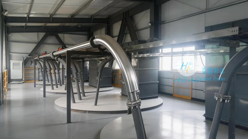
The first step in designing a heavy powder pneumatic conveying system involves selecting the appropriate system type based on the material's physical properties and the required transport distance. There are primarily two types of pneumatic conveying systems: dilute-phase and dense-phase. Dilute-phase systems use high-velocity air to suspend the powder particles, suitable for short to medium distances and low to moderate particle sizes. Dense-phase systems, on the other hand, use lower air velocities and higher pressure to transport the material in a slurry-like state, ideal for longer distances and more abrasive or sensitive powders. Understanding the material's density, particle size distribution, moisture content, and flowability is essential to determine the most suitable system. For example, materials with high moisture content may require special considerations to prevent caking or blockages, while abrasive powders demand robust equipment to withstand wear and tear.
Key Design Parameters and Calculations
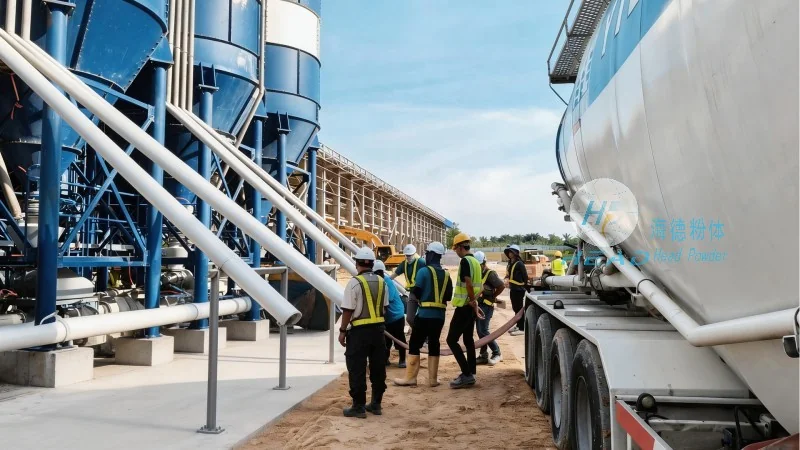
Several critical parameters must be calculated to ensure the system operates efficiently and safely. The first is the required air velocity, which must be sufficient to keep the powder particles suspended but not so high as to cause excessive energy consumption or equipment wear. The air velocity is typically determined by the material's terminal velocity, which is the speed at which a particle falls through the air under gravity. The formula for terminal velocity (Vt) is given by Stokes' law for spherical particles: Vt = (2r^2(ρp - ρf)g) / (9μ), where r is the particle radius, ρp is the particle density, ρf is the fluid density (air), g is the acceleration due to gravity, and μ is the fluid viscosity. This calculation helps in determining the minimum air velocity needed to prevent particle settling. Another important parameter is the system's pressure drop, which affects the energy consumption and the overall system performance. The pressure drop (ΔP) across the conveying line can be estimated using the Darcy-Weisbach equation: ΔP = f (L/D) (ρf V^2 / 2), where f is the friction factor, L is the pipe length, D is the pipe diameter, and V is the air velocity. Proper calculation of these parameters ensures that the system operates within its design limits and meets the required transport capacity.
Equipment Selection and Component Integration
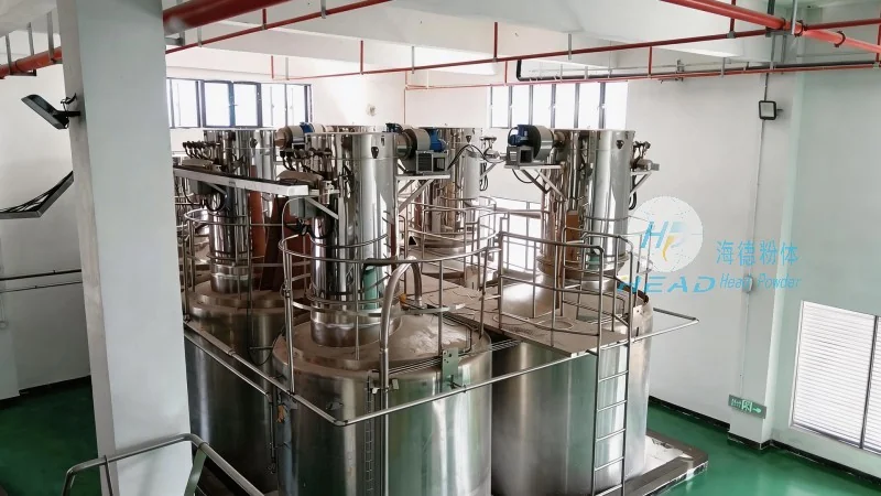
Choosing the right equipment components is crucial for the system's performance and longevity. The main components of a pneumatic conveying system include the material feeder, the conveying line, the air source (blower or compressor), and the control system. The material feeder must be capable of feeding the powder at a consistent rate without causing blockages or fluctuations. For heavy powders, screw feeders or rotary valves are commonly used due to their ability to handle high bulk densities and prevent material bridging. The conveying line is typically made of stainless steel or other corrosion-resistant materials to withstand the abrasive nature of the powder and prevent wear. The pipe diameter is selected based on the required air velocity and the material's flow rate, ensuring that the line is neither too small (leading to high pressure drop) nor too large (leading to excessive energy consumption). The air source must provide sufficient pressure and flow rate to meet the system's requirements. Centrifugal blowers are often preferred for dilute-phase systems due to their high airflow capacity and lower cost, while positive displacement blowers are used for dense-phase systems to achieve higher pressures. The control system, which includes sensors and valves, is responsible for monitoring and adjusting the system's operation in real-time, ensuring stable and efficient transport. For example, pressure sensors can detect blockages or changes in flow rate, triggering alarms or automatic shutdowns to prevent equipment damage.
Installation and Maintenance Considerations
Proper installation and regular maintenance are essential to ensure the long-term reliability of the pneumatic conveying system. During installation, it is important to consider the layout of the conveying line, ensuring that it is as straight as possible to minimize pressure drop and avoid sharp bends that can cause particle accumulation or wear. The line should also be equipped with appropriate fittings, such as elbows and tees, to facilitate changes in direction and branching. Regular maintenance is crucial to prevent system failures and extend equipment life. This includes cleaning the material feeder and conveying line to remove accumulated powder, inspecting the air source and control system for wear or damage, and replacing worn parts such as seals and bearings. For heavy powders, especially those that are abrasive or have high moisture content, more frequent maintenance may be required to prevent equipment wear and maintain system performance. Proper maintenance also helps in identifying potential issues early, allowing for timely repairs and minimizing downtime.
Case Study: Heavy Powder Conveying in Cement Industry
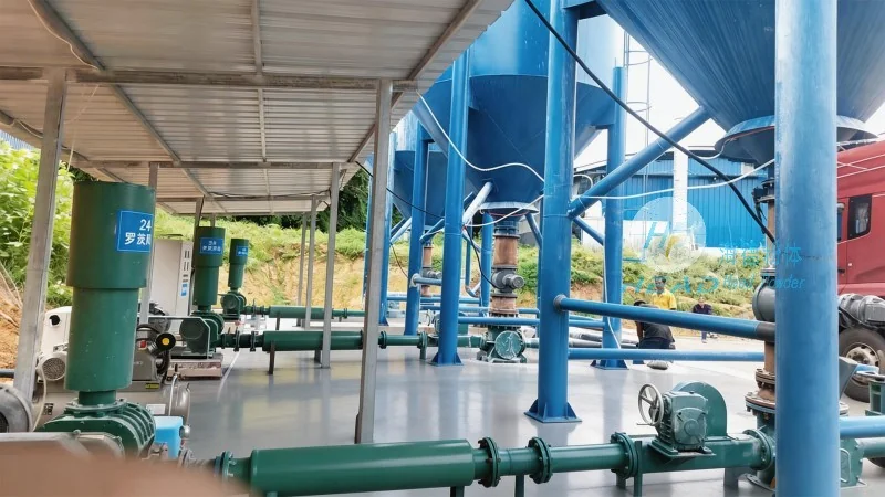
Shandong HeadPowder Engineering Co., Ltd. has successfully implemented heavy powder pneumatic conveying systems in various industrial sectors, including the cement industry. In one project, the company designed and installed a dense-phase pneumatic conveying system to transport raw materials from a storage silo to a cement production plant. The system was designed to handle a high bulk density of 1.5 tons per cubic meter and a particle size range of 0.1 to 5 mm. The material feeder was a rotary valve with a capacity of 10 tons per hour, and the conveying line was made of stainless steel with a diameter of 200 mm. The air source was a positive displacement blower with a pressure of 0.8 MPa and a flow rate of 10 m³/min. The system was installed with a control system that monitored the pressure and flow rate in real-time. The project was completed successfully, with the system achieving a transport efficiency of 98% and a pressure drop of 0.5 MPa across the line. The system has been in operation for over two years, with minimal maintenance required, demonstrating the effectiveness of the design and the reliability of the equipment.